
Microelectronics: Circuit Analysis and Design
4th Edition
ISBN: 9780073380643
Author: Donald A. Neamen
Publisher: McGraw-Hill Companies, The
expand_more
expand_more
format_list_bulleted
Videos
Textbook Question
Chapter 7, Problem 7.22P
(a) For the circuit shown in Figure P7.22, write the voltage transfer function
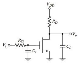
Figure P7.22
Expert Solution & Answer
Want to see the full answer?
Check out a sample textbook solution
Students have asked these similar questions
19)This MCQ QUESTION FROM ANTENNA ENGINEERING course.
There exist several methods to perform AM demodulation, consider a requirement where we intend to design an AM receiver which is characterized by less distortion and high SNR.Identify which type of AM demodulation scheme is mentioned in the above statement and explain one such demodulation with appropriate sketch.Compare and contrast different AM modulation and demodulation schemes in various aspectsExplore one interesting application area involving Amplitude Modulation with explanation and neat sketch.
1.Select the correct statement(s) regarding frequency modulation (FM) bandwidth.
a. the more the carrier frequency is allowed to change frequencies (Δf), the smaller the modulated signal bandwidth
b. the larger the FM index, β, the larger the modulated signal bandwidth
c. as you increase kvco, you decrease modulated signal bandwidth
d. all statements are correct
2. Select the correct statement(s) regarding baseband signal modulation.
a. with modulation, a baseband signal can be moved to a higher frequency thus preventing baseband signal interference
b. modulation techniques are only required for analog information signals, since digital signals are represented by discrete logical values of “1” and “0”
c. modulation eliminates the baseband signal’s frequency bandwidth, thus enabling greater efficiencies when transmitting a modulated carrier signal
d. all statements are correct
3. A…
Chapter 7 Solutions
Microelectronics: Circuit Analysis and Design
Ch. 7 - (a) For the circuit shown in Figure 7.2, the...Ch. 7 - The circuit shown in Figure 7.10 has parameters of...Ch. 7 - For the equivalent circuit shown in Figure 7.13,...Ch. 7 - The equivalent circuit in Figure 7.14 has circuit...Ch. 7 - The parameters in the circuit shown in Figure 7.15...Ch. 7 - For the circuit shown in Figure 7.2 1(a), the...Ch. 7 - Consider the circuit shown in Figure 7.22(a). The...Ch. 7 - For the emitterfollower circuit shown in Figure...Ch. 7 - The circuit shown in Figure 7.27(a) has parameters...Ch. 7 - Consider the common-base circuit shown in Figure...
Ch. 7 - The commonemitter circuit shown in Figure 7.34...Ch. 7 - A bipolar transistor has parameters o=120 ,...Ch. 7 - Prob. 7.9EPCh. 7 - For the circuit in Figure 7.41(a), the parameters...Ch. 7 - A bipolar transistor is biased at ICQ=120A and its...Ch. 7 - For the transistor described in Example 7.9 and...Ch. 7 - The parameters of a bipolar transistor are: o=150...Ch. 7 - The parameters of an nchannel MOSFET are...Ch. 7 - For the circuit in Figure 7.55, the transistor...Ch. 7 - An nchannel MOSFET has parameters Kn=0.4mA/V2 ,...Ch. 7 - An nchannel MOSFET has a unitygain bandwidth of...Ch. 7 - For a MOSFET, assume that gm=1.2mA/V . The basic...Ch. 7 - The transistor in the circuit in Figure 7.60 has...Ch. 7 - Consider the commonbase circuit in Figure 7.64....Ch. 7 - The cascode circuit in Figure 7.65 has parameters...Ch. 7 - Prob. 7.12TYUCh. 7 - For the circuit in Figure 7.72, the transistor...Ch. 7 - Describe the general frequency response of an...Ch. 7 - Describe the general characteristics of the...Ch. 7 - Describe what is meant by a system transfer...Ch. 7 - What is the criterion that defines a corner, or...Ch. 7 - Describe what is meant by the phase of the...Ch. 7 - Describe the time constant technique for...Ch. 7 - Describe the general frequency response of a...Ch. 7 - Sketch the expanded hybrid model of the BJT.Ch. 7 - Prob. 9RQCh. 7 - Prob. 10RQCh. 7 - Prob. 11RQCh. 7 - Sketch the expanded smallsignal equivalent circuit...Ch. 7 - Define the cutoff frequency for a MOSFET.Ch. 7 - Prob. 14RQCh. 7 - Why is there not a Miller effect in a commonbase...Ch. 7 - Describe the configuration of a cascode amplifier.Ch. 7 - Why is the bandwidth of a cascode amplifier...Ch. 7 - Why is the bandwidth of the emitterfollower...Ch. 7 - Prob. 7.1PCh. 7 - Prob. 7.2PCh. 7 - Consider the circuit in Figure P7.3. (a) Derive...Ch. 7 - Consider the circuit in Figure P7.4 with a signal...Ch. 7 - Consider the circuit shown in Figure P7.5. (a)...Ch. 7 - A voltage transfer function is given by...Ch. 7 - Sketch the Bode magnitude plots for the following...Ch. 7 - (a) Determine the transfer function corresponding...Ch. 7 - Consider the circuit shown in Figure 7.15 with...Ch. 7 - For the circuit shown in Figure P7.12, the...Ch. 7 - The circuit shown in Figure 7.10 has parameters...Ch. 7 - The transistor shown in Figure P7.14 has...Ch. 7 - Consider the circuit shown in Figure P7.15. The...Ch. 7 - The transistor in the circuit shown in Figure...Ch. 7 - For the common-emitter circuit in Figure P7.17,...Ch. 7 - The transistor in the circuit in Figure P7.20 has...Ch. 7 - For the circuit in Figure P7.21, the transistor...Ch. 7 - (a) For the circuit shown in Figure P7.22, write...Ch. 7 - Consider the circuit shown in Figure P7.23. (a)...Ch. 7 - The parameters of the transistor in the circuit in...Ch. 7 - A capacitor is placed in parallel with RL in the...Ch. 7 - The parameters of the transistor in the circuit in...Ch. 7 - Prob. D7.27PCh. 7 - The circuit in Figure P7.28 is a simple output...Ch. 7 - Reconsider the circuit in Figure P728. The...Ch. 7 - Consider the circuit shown in Figure P7.32. The...Ch. 7 - The commonemitter circuit in Figure P7.35 has an...Ch. 7 - Consider the commonbase circuit in Figure 7.33 in...Ch. 7 - Prob. 7.39PCh. 7 - The parameters of the transistor in the circuit in...Ch. 7 - In the commonsource amplifier in Figure 7.25(a) in...Ch. 7 - A bipolar transistor has fT=4GHz , o=120 , and...Ch. 7 - A highfrequency bipolar transistor is biased at...Ch. 7 - (a) The frequency fT of a bipolar transistor is...Ch. 7 - The circuit in Figure P7.48 is a hybrid ...Ch. 7 - Consider the circuit in Figure P7.49. Calculate...Ch. 7 - A common-emitter equivalent circuit is shown in...Ch. 7 - For the common-emitter circuit in Figure 7.41(a)...Ch. 7 - For the commonemitter circuit in Figure P7.52,...Ch. 7 - Consider the circuit in Figure P7.52. The resistor...Ch. 7 - The parameters of the circuit shown in Figure...Ch. 7 - The parameters of an nchannel MOSFET are kn=80A/V2...Ch. 7 - Find fT for a MOSFET biased at IDQ=120A and...Ch. 7 - Fill in the missing parameter values in the...Ch. 7 - (a) An nchannel MOSFET has an electron mobility of...Ch. 7 - A commonsource equivalent circuit is shown in...Ch. 7 - Prob. 7.60PCh. 7 - The parameters of an ideal nchannel MOSFET are...Ch. 7 - Figure P7.62 shows the highfrequency equivalent...Ch. 7 - For the FET circuit in Figure P7.63, the...Ch. 7 - The midband voltage gain of a commonsource MOSFET...Ch. 7 - Prob. 7.65PCh. 7 - Prob. 7.67PCh. 7 - The bias voltages of the circuit shown in Figure...Ch. 7 - For the PMOS commonsource circuit shown in Figure...Ch. 7 - In the commonbase circuit shown in Figure P7.70,...Ch. 7 - Repeat Problem 7.70 for the commonbase circuit in...Ch. 7 - In the commongate circuit in Figure P7.72, the...
Knowledge Booster


Learn more about
Need a deep-dive on the concept behind this application? Look no further. Learn more about this topic, electrical-engineering and related others by exploring similar questions and additional content below.Similar questions
- A carrier is modulated simultaneously by two baseband signals with modulation indices of 0.3 and 0.4 respectively. If the scheme is AM, then what will the overall modulation index?arrow_forwardQ3 (i) What do you mean by baseband transmission of a digital signal ? What are the possible types of connection of devices in a topology for communication?arrow_forward5. Why must modulated signals be demodulated?A. To recover the original intelligenceB. To improve the spectral efficiency of digital transmissionsC. To enable implementation of advanced featuresD. To produce one or more significant sideband pairsarrow_forward
- a) Sketch the spectrum of g(t)?b) Sketch the spectrum at point (a) of the conversion system?c) What should the parameter w0 be relative to wc?d) What should be the value of passband gain A?arrow_forwardIt is given as ?1 = ?3 = 50Ω and ?2 = 25Ω in the two-gate Π circuit given in the figure. According to this,a) Find the scattering matrix of the two-port circuit Π.b) Using the scattering matrix in a), determine the properties provided by the two-port circuit.arrow_forward(a) Write the expression for the output voltage for the Jones mixer as shown for IBB =2 mA, Vm= 10 mV, RC = 5 kΩ, 2R1 = 1 kΩ, fc = 90 MHz, and fm = 10 MHz. Include the terms for n = 1 and 2. (b) What is the largest value of V1 that satsifies our small-signal assumption?arrow_forward
- 1. Select the correct statement(s) regarding amplitude modulation (AM). a. If the AM Index is greater than 1 (i.e., µAM>1), then over modulation occurs leading to signal distortion b. With AM, the message is captured as amplitude changes to the carrier’s amplitude. c. The AM modulated carrier bandwidth is dependent upon the baseband signal’s frequency bandwidth d. All of the above are correct 2. What is true about the frequency bandwidth of a modulated electrical or electromagnetic (EM) signal? a. signal bandwidth is only determined by the frequency of the unmodulated carrier wave b. modulation technique and the amount of information transmitted determines the signal’s bandwidth c. only the baseband signal determines frequency bandwidth; i.e., modulation technique has no impact on bandwidth d. a and c are true 3.Regarding carrier modulation, identify the carrier signal variable(s)…arrow_forwardWhat are the advantages and disadvantages of single-sideband transmission? Briefly describe each.arrow_forwardHow many channels are available in the 5 GHz band? List all the channels. What is the channel bandwidth?arrow_forward
- 2 (AM) A 10 V amplitude sinusoidal signal is used as a modulating signal to generate an AM signal with modulation index 0.8. What is the amplitude of the carrier? What is the power of the side bands? What is the efficiency of the modulated signal?arrow_forward5. The following data is available: fc= carrier frequency = 750kHz, Ac= maximum amplitude of the unmodulated carrier = 10V fm= modulator frequency = 300Hz-8kHz modulation index m=0.5 a) What is the frequency of the upper sideband? b) What is the frequency of the lower sideband? c) What is the amplitude of the modulating signal? d) What is the maximum amplitude of the envelope of the modulated signal? e) What is the minimum amplitude of the envelope of the modulated signal? f) What is the bandwidth of the modulated wave? g) Write an expression for the modulated wavearrow_forwardAn analog signal is given as?(?) = 5 + 2 cos(20??) + 3 cos(400??)a) What is the bandwidth of ?(?)? Determine the Nyquist sampling frequency for ?(?), both in radian/sec (?? ), and in Hz (?? ).b) Formulate ?? (??), the signal sampled with the Nyquist frequency.c) Plot frequency spectrum of the sampled signal, ?? (??).d) Determine the filter to reconstruct the signal ?(?).e) Is it possible to reconstruct the signal ?(?) for ?? = 0.004 [s]? State that if aliasing error occurs or not.arrow_forward
arrow_back_ios
SEE MORE QUESTIONS
arrow_forward_ios
Recommended textbooks for you
 Introductory Circuit Analysis (13th Edition)Electrical EngineeringISBN:9780133923605Author:Robert L. BoylestadPublisher:PEARSON
 Delmar's Standard Textbook Of ElectricityElectrical EngineeringISBN:9781337900348Author:Stephen L. HermanPublisher:Cengage Learning
 Programmable Logic ControllersElectrical EngineeringISBN:9780073373843Author:Frank D. PetruzellaPublisher:McGraw-Hill Education
 Fundamentals of Electric CircuitsElectrical EngineeringISBN:9780078028229Author:Charles K Alexander, Matthew SadikuPublisher:McGraw-Hill Education
 Electric Circuits. (11th Edition)Electrical EngineeringISBN:9780134746968Author:James W. Nilsson, Susan RiedelPublisher:PEARSON
 Engineering ElectromagneticsElectrical EngineeringISBN:9780078028151Author:Hayt, William H. (william Hart), Jr, BUCK, John A.Publisher:Mcgraw-hill Education,
Introductory Circuit Analysis (13th Edition)
Electrical Engineering
ISBN:9780133923605
Author:Robert L. Boylestad
Publisher:PEARSON
Delmar's Standard Textbook Of Electricity
Electrical Engineering
ISBN:9781337900348
Author:Stephen L. Herman
Publisher:Cengage Learning
Programmable Logic Controllers
Electrical Engineering
ISBN:9780073373843
Author:Frank D. Petruzella
Publisher:McGraw-Hill Education
Fundamentals of Electric Circuits
Electrical Engineering
ISBN:9780078028229
Author:Charles K Alexander, Matthew Sadiku
Publisher:McGraw-Hill Education
Electric Circuits. (11th Edition)
Electrical Engineering
ISBN:9780134746968
Author:James W. Nilsson, Susan Riedel
Publisher:PEARSON
Engineering Electromagnetics
Electrical Engineering
ISBN:9780078028151
Author:Hayt, William H. (william Hart), Jr, BUCK, John A.
Publisher:Mcgraw-hill Education,
Huffman Codes: An Information Theory Perspective; Author: Reducible;https://www.youtube.com/watch?v=B3y0RsVCyrw;License: Standard Youtube License