
Videos
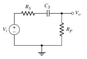
(a) For the circuit shown in Figure 7.2, the parameters are
(b) Consider the circuit shown in Figure 7.3 with parameters
(a).
The value of the capacitor
Answer to Problem 7.1EP
Explanation of Solution
Given Information:
The given circuit is shown below.
Calculation:
(i).
The value of coupling capacitor
The expression of lower cutoff frequency is:
(ii).
The transfer function of the circuit is determined as follows:
(b).
The value of the corner frequency
Answer to Problem 7.1EP
Explanation of Solution
Given Information:
The given circuit is shown below.
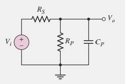
Calculation:
The value of time constant of the circuit is:
The value of corner frequency is determined as follows:
The transfer function of the circuit is determined as follows:
Want to see more full solutions like this?
Chapter 7 Solutions
Microelectronics: Circuit Analysis and Design


- Obtain the observable canonical state space form of the system whose pulse transfer function is given below.please payarrow_forwardIn the circuit shown in the figure, Vcc = 12 V, Vin = 10 mV, β = 100, r0 = 40 kΩ, RB = 360 kΩ, RC = 3.3 kΩ, RE = 220 Ω, Rs = 0.5 kΩ and RL = 7.1 kΩ . Accordingly, find the voltage gain (Vout/Vin) of the circuit. NOTE-1: The output impedance of the transistor r0 will be taken into account in the calculations.NOTE-2: Capacitors are negligible at midband frequency.arrow_forwardA superheterodyne receiver is to tune the range 88.1MHz to 107.1MHz. The RF circuit inductance is 1μH. Low-side injection is used.a. Calculate the minimum capacitance of the variable capacitor in the RF circuitb. Calculate the RF circuit capacitance tuning ratio c. If the receiver has a single converter stage and IF of 800kHz, calculate the capacitance tuning ratio of the local oscillator d. If the maximum capacitance of the variable capacitor of the local oscillator is 0.2pF, calculate the minimum capacitance e. If the receiver has a single converter stage and IF of 800kHz, calculate the image frequency of 103.7MHzf. Calculate the IFRR (in dB) of (e) if Q of the preselector is 50 g. To increase the IFRR of (e) to 40dB, double conversion is used. What must be the frequency of the 1st IF?arrow_forward
- Determine the energy content of the even symmetric component of the signal defined asx(t) = 10+2t volts, -5≤t≤5= 0, otherwisearrow_forwardi) A communication system employs a continuous source. The channel noise is white and Gaussian. The bandwidth of the source output is 10 MHz and signal to noise power ratio at the receiver is 100. (a) Determine the channel capacity. (b) If the signal to noise ratio drops to 10, how much bandwidth is needed to achieve the same channel capacity as in (a). (c) If the bandwidth is decreased to 1 MHz, what S/N ratio is required to maintain the same channel capacity as in (a).arrow_forwardIn the circuit shown in the figure, Vcc = 12 V, Vin = 10 mV, β = 100, r0 = 40 kΩ, RB = 360 kΩ, RC = 3.3 kΩ, RE = 220 Ω, Rs = 0.5 kΩ and RL = 42.1 kΩ . Accordingly, find the voltage gain (Vout/Vin) of the circuit.NOTE-1: The output impedance of the transistor r0 will be taken into account in the calculations.NOTE-2: Capacitors are negligible at midband frequency.arrow_forward
- a. An AM transmitter has the unmodulated carrier power of 20kW and can be modulated to a maximum of 70% before the system saturates/overloads. Find the value to which carrier power can be increased if 40% modulation limit is imposed.b. An analog communication system using FM has the highest modulating frequency of 5 kHz and maximum deviation of 25 kHz. Calculate the bandwidth of modulated signal using Carson’s rule. Compare this value with the one obtained using the simple formula. For practical systems which of these values should be used?arrow_forwardElectronic Since k = 0.35x10^3, VGSQ = 6.2 V, VGS(Th) = 2.4 V, RF = 100 MΩ, RG = 10 MΩ, RD = 7.6 kΩ, RS = 2.2 kΩ and RL = 21 kΩ in the circuit in the figure, the output voltage In which option is the amplitude value (Vout) given correctly? NOTE-1: E-MOSFET output impedance is rd = 70 kΩ and should be taken into account in calculations. NOTE-2: Capacitors are of negligible size at mid-band frequency. NOTE-3: It is within the 5 kHz mid-band frequency.arrow_forwardA shield that contains 10 identical apertures in a linear array is required to have30 dB of shielding effectiveness at 100 MHz. Determine the maximum lineardimension of one aperture.arrow_forward
- Problem 1 The transistor parameters for the given circuit are β = 100, VBE (on) = 0.7 V, and VA = ∞. Determine the midband gain AvM, corner frequencies fL and fH, and bandwidth BW of the given amplifier. Problem 2 Determine the corner frequencies and limiting horizontal asymptotes of a commonemitter amplifier with an emitter bypass capacitor. For the given circuit, RE = 4 kΩ, RC = 2 kΩ, RS = 0.5 kΩ, CE = 1 μF, V + = 5 V, and V − = −5 V. The transistor parameters are: β = 100, VBE(on) = 0.7 V, and ro = ∞.arrow_forwardThe following information is given for the two – branch parallel circuit as shown in the figure in which it is assumed that RC is negligibly small or zero: RL = 8 ohms, XL (at 400 cps) = 7.53 ohms, XC (at 400 cps)= 19.9 ohms, V = 30 volts. Calculate (a) the resonant frequency of the circuit, (b) the line current, (c) the inductor and capacitor branch currents.arrow_forwardi.Discuss the rationale behind the application of FM for indigenouscommunication. ii. Explain why receivers are very unique in their functions. Discuss allaspects of their uniqueness. iii. Explain in detail the essential things that happen to the modulating signalbefore transmission. Discuss all types or kinds available if necessary. Notethat without these essential systems, transmission will not be able to besent to yield the needed result.arrow_forward
 Introductory Circuit Analysis (13th Edition)Electrical EngineeringISBN:9780133923605Author:Robert L. BoylestadPublisher:PEARSON
 Delmar's Standard Textbook Of ElectricityElectrical EngineeringISBN:9781337900348Author:Stephen L. HermanPublisher:Cengage Learning
 Programmable Logic ControllersElectrical EngineeringISBN:9780073373843Author:Frank D. PetruzellaPublisher:McGraw-Hill Education
 Fundamentals of Electric CircuitsElectrical EngineeringISBN:9780078028229Author:Charles K Alexander, Matthew SadikuPublisher:McGraw-Hill Education
 Electric Circuits. (11th Edition)Electrical EngineeringISBN:9780134746968Author:James W. Nilsson, Susan RiedelPublisher:PEARSON
 Engineering ElectromagneticsElectrical EngineeringISBN:9780078028151Author:Hayt, William H. (william Hart), Jr, BUCK, John A.Publisher:Mcgraw-hill Education,