
Videos
Figure P8.18a shows a uniform beam subject to a linearly increasing distributed load. The equation for the resulting elastic curve is (see Fig. P8.18b)
Use bisection to determine the point of maximum deflection (that is, the value of
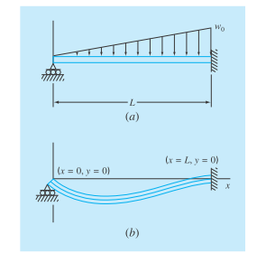
FIGURE P8.18
Want to see the full answer?
Check out a sample textbook solution
Chapter 8 Solutions
EBK NUMERICAL METHODS FOR ENGINEERS
Additional Engineering Textbook Solutions
Advanced Engineering Mathematics
Fundamentals of Differential Equations (9th Edition)
Basic Technical Mathematics
Pre-Algebra Student Edition
Algebra 1


- Problem 4 The overhanging steel beam ABC carries a concentrated load P at end C. For portion AB of the beam, (a) derive the equation of the elastic curve, (b) determine the maximum deflection, (c) evaluate vmax for the following data: W14 × 68 | = 722 in4 E = 29 x 106 psi P = 50 kips L = 15 ft = 180 in. %3D a = 4 ft = 48 in %3D х- -by- Flange Web Thick- Thick- Axis X-X Axis Y-Y Depth d, in. Area Width ness ness Designation' A, in? br, in. to, in. L in. in S, in F in. in' S, in in. W14 x 370 109 17.9 16.5 2.66 1.66 5440 607 7.07 1990 241 4.27 145 42.7 14.8 15.5 1.09 0.680 1710 232 6.33 677 87.3 3.98 82 24.0 14.3 10.1 0.855 0.510 881 123 6.05 148 29.3 2.48 68 20.0 14.0 10.0 0.720 0.415 722 103 6.01 121 24.2 2.46 53 15.6 13.9 8.06 0.660 0.370 541 77.8 5.89 57.7 14.3 1.92 43 12.6 13.7 8.00 0.530 0.305 428 62.6 5.82 45.2 11.3 1.89 6.77 0.515 0.310 385 54.6 5.87 26.7 7.88 1.55 38 11.2 14.1 *You can draw a FBD, Shear V-diagram, and a Bending Moment-M diagram to help in determining the shear…arrow_forwardA beam has a bending moment of 3 kN-m applied to a section with a hollow circular cross-section of external diameter 3.4 cm and internal diameter 2.4 cm . The modulus of elasticity for the material is 210 x 109 N/m2. Calculate the radius of curvature and maximum bending stress. Also, calculate the stress at the point at 0.6 cm from the neutral axis (i) The moment of inertia (mm^4)= ii) The radius of curvature is (mm)= (iii) The maximum bending stress is(N/mm^2)= iv) The bending stress at the point 0.6 cm from the neutral axis is(N/mm^2) =arrow_forwardQuestion 3 The statically indeterminate beam shown in Fig. 3 has flexural rigidity El=4 MN-m². A is fully fixed and B is supported by a roller. P=14KN and w=7kN/m. Using Macauley's double integration method, 1) Calculate the reaction force at support B. 2) Calculate the reaction force at support B when the support B settles vertically downward through a distance of 8.0mm. C Flm- 2m +1 m→-1 m Fig. 3arrow_forward
- A I-meter-long, simply supported copper beam (E= 117 GPa) carries uniformly distributed load q. The maximum deflection is measured as 1.5 mm. a. Calculate the magnitude of the distributed load q if the beam has a rectangular cross section (width b= 20 mm, height h= 40 mm). b. If instead the beam has circular cross section and q= 500 N/m, calculate the radius r of the cross section. Neglect the weight of the beam.arrow_forward1. Find the resultant force in a brass beam from a normal stress of 98 MN/m2 with a square cross-section (s = 12 mm). 2. What is the maximum shear stress for a silicone beam (d = 10 cm) resulting in a maximum shear load of 3 MN?arrow_forwardrequest 3.3 A T-shaped cross-section beam is loaded as shown in Figure P8.11. Find the maximum tensile and compressive stresses that occur in the beam. w = 80 kN/m -1 m- m- M = 20 kN-m Figure P8.11 50 mm \P = 30 kN 100 mm 150 mm -25 mmarrow_forward
- A beam has a bending moment of 2 kN-m applied to a section with a hollow circular cross-section of external diameter 3.2 cm and internal diameter 2 cm. The modulus of elasticity for the material is 210 x 10° N/m2. Calculate the radius of curvature and maximum bending stress. Also, calculate the stress at the point at 0.5 cm from the neutral axis Solution: (i) The moment of inertia = ii) The radius of curvature is (iii) The maximum bending stress is iv) The bending stress at the point 0.5 cm from the neutral axis isarrow_forwardExample 5: Draw the shear force and bending moment diagrams for the simply supported beam as shown below. 400 N 500 N 300 N to A E 3m 4m 4m 5marrow_forwardA solid circular cross-section beam with length, L is subjected to a pure torsion T = 0.5 F(Nm) and a tensile load P = 5F N. Find the maximum value of F that can be applied to thebeam with a safety factor of 2.5 using;i) Maximum shear stress theoryii) Shear/distortion energy theory(Beam is made of steel with a diameter of 50 mm, L= 1.5 m, E = 200 GPa, Y = 250 MPa, v =0.29)arrow_forward
- A beam of uniform rectangular section 200 mm wide and 300 mm deep is simply supported at its ends. It carries a uniformly distributed load of 9 KN/m run over the entire span of 5 m. if the value of E for the beam material is 1 X 10⁴ N/mm2 , find the slope at the supports and maximum deflection. Give me complete solution based on the given above. Again I need to ask the same question since you gave me a wrong answer before.arrow_forwardA rectangular beam with two notches (with radius r = 2.5 mm) is shown in Figure 1.1. The beam has dimensions w = 55 mm and d = 50 mm. The beam is subjected to a bending moment of M = 1.3 kNm and the maximum allowable bending stress in the material is 400 MPa. Determine the smallest thickness, tmin, in mm that this beam should be designed for. Stress concentration graph is provided in Figure 1.2. K₁ M 3.0 2.6 2.2 1.8 1.4 16 1.0 0 1.10 1.05 1.02 0.05 wld = ∞ W 1.5 0.10 Figure 1.1. 0.15 rld Figure 1.2. Inom 0.20 6M td² 0.25 M M 0.30arrow_forwardA built-in cantilever beam with a hollow rectangular cross-section is subjected to a uniformly distributed load as shown in Figure Q1 below. Which of the following statements best describes the shear force variation along the length, in the x direction, using the sign conventions provided in lectures? Figure Q1 QUESTION 5 For the same beam and loading case in Figure Q1, when finding the vertical deflecion for any point along its length, v, what combination of boundary conditions COULD be applied? OWhen =0,- dv ANDL. dr Ob.When 0,v=0 AND 0, dr Oc When 0,vm0 AND =L,v=0 Od.When L. dv --AND de X=L.v=0 Oe. None of the provided answers are correctarrow_forward
 Elements Of ElectromagneticsMechanical EngineeringISBN:9780190698614Author:Sadiku, Matthew N. O.Publisher:Oxford University Press
 Mechanics of Materials (10th Edition)Mechanical EngineeringISBN:9780134319650Author:Russell C. HibbelerPublisher:PEARSON
 Thermodynamics: An Engineering ApproachMechanical EngineeringISBN:9781259822674Author:Yunus A. Cengel Dr., Michael A. BolesPublisher:McGraw-Hill Education
 Control Systems EngineeringMechanical EngineeringISBN:9781118170519Author:Norman S. NisePublisher:WILEY
 Mechanics of Materials (MindTap Course List)Mechanical EngineeringISBN:9781337093347Author:Barry J. Goodno, James M. GerePublisher:Cengage Learning
 Engineering Mechanics: StaticsMechanical EngineeringISBN:9781118807330Author:James L. Meriam, L. G. Kraige, J. N. BoltonPublisher:WILEY