
Videos
A simply supported beam is loaded as shown in Fig. P8.24. Using singularity functions, the shear along the beam can be expressed by the equation:
By definition, the singularity function can be expressed as follows:
Use a numerical method to find the point(s) where the shear equals zero.
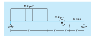
FIGURE P8.24
Want to see the full answer?
Check out a sample textbook solution
Chapter 8 Solutions
EBK NUMERICAL METHODS FOR ENGINEERS
Additional Engineering Textbook Solutions
Fundamentals of Differential Equations (9th Edition)
Basic Technical Mathematics
Advanced Engineering Mathematics
Precalculus: Mathematics for Calculus - 6th Edition
College Algebra (7th Edition)


- When a beam section is subjected to a shear load, a shear stress distribution is developed on the section. The distribution of the shear stress is not linear. Elasticity theory can be used to calculate the shear stress at any point. However, a simpler method can be used to calculate the average shear stress across the width of the section, a distance y above or below the neutral axis. The average VQ shear stress is given by T = Here V is the shear It force on the section, I is the moment of inertia of the entire section about the neutral axis, and t is the width of the section at the distance y where the shear stress is being calculated. Q is the product of the area of the section above (or below) y and the distance from the neutral axis to the centroid of that area (Figure 1). In short, Q is the moment of the area about the neutral axis. I Figure 1 of 1 An I-beam has a flange width b = 250 mm, height h = 250 mm, web thickness tw = 9 mm, and flange thickness tf = 14 mm. Use the…arrow_forwardThe basic differential equation of the elastic curve for a simply supported, uniformly loaded beam is given as: wLx wx ... dx 2 where E is the modulus of elasticity and I is the moment of inertia. The boundary conditions are y(0)=y(L)=0. Determine the deflection of the beam at point with maximum deflection using any method if E=200 GPa, l=30,000 cm^4, w=15 kN/m and L=3 m. by considering the equation as shown below: wLx3 y = wx+ wL3x ... 12EI 24EI 24EI Express your answer (absolute numerical value) in millimeter and up to four decimal digits after the decimal point. The answer is Blank 1 Blank 1 Add your answerarrow_forward(A) An engineer designing a bridge with pieces of 12 m long simply supported beam of flexural rigidity, El = 210 GNmm2, wants you to determine: %3D i. the slope on the beam 2 m away from any end and ii. the deflection, y, at the centre of the beam, if the bending moment of the beam M, with uniformly distributed load, is expressed as M = El y" where M is: M = 30x – 12x? NOTE: No deflection at the supports and it slope is maximum at the centre.arrow_forward
- 0.0062 0.0025 0.0012 Let D = 0.0025 0.0049 0.0025 be a flexibility matrix, with flexibility measured in inches per pound. Suppose that forces of 40, 10, and 0.0012 0.0025 0.0062 20 lb are applied to a beam at points 1, 2, and 3, respectively. Find the corresponding deflections y₁, y₂, and y3. #1 #3 1 3₂ £₂ Y₁ = inch(es) (Round to the nearest thousandth as needed.) Y3arrow_forwardQ7\ Draw the shear-force and bending-moment diagrams for a beam shown below 2 kN/m 6kN/m 12 kN 4,0 m 2.0 m VA Q8\ sketch the axial load, shear force and bending moment diagrams. 12 kN 16 kN/m 12 kN 16 kN B 6 kN/m D Hp 5.0 m t 8.0 m VA 3.0 m VDarrow_forward15 A cantilever beam of uniform cross section and length L bears a concentrated load P at its free end. A tensile force F also acts at the free end in the direction of the undeflected beam. By choosing coordinates as shown in Fig. 2.9, find the equation of the deflection curve of the beam, and the deflection of the free end relative to the fixed end. P (х. у) F +arrow_forward
- Q10 \ sketch the axial load, shear force and bending moment diagrams. 10KN/m ITIIII 3im 2 'm J60KN 60KN] 4;m 23.3 23.3 120 120arrow_forwardUsing singularity functions, develop an expression for the bending moment M(x) asfunction of position (x) along the beam.arrow_forwardmhm 4.31 System for Exercise 4.24 (left) and Exercise 4.25 (right). m, the force required to deflect the end, as is illustrated in Figure 4.32 is In Chapter 11 we are much smarter and are able to show that for a cantilever ЗЕЛ L3 X, 4.32 Cantilever beam subjected to a at the end. F = ere E is the modulus of elasticity, which is a property of the material used, I is area moment of inertia of the cross-section of the beam, and L is the length. If a mass m,is attached to the end of the beam, what is the equation of motion the vertical motion of the beam? If the length is doubled, what is the change in quency of the free vibration of the beam? =kX 2 Guieds x=0 F-XX F x = L Fig. 4.33 Rotatin 4.28. Referring the end of a ca elasticity of the length is L = 1 1. Determine t 2. Determine t @= 1000 r 4.29. Determin 1. On the sam 2. Identify the the part youarrow_forward
- For the simply-supported and cantilever beams given below, use Singularity Functions to determine slope and displacement equations. Provide graphs of both slope and displacement versus position along the beam. A A 5 ft B * B 5 ft 5 ft 27 kips E 20 ft 45 kip-ft 11 kips 5 ft 3.5 kips/ft 20 ft C 5 ft 5 ft 2.3 kips/ft 5 ft ]c S ft Darrow_forwardA Please enter your supplied question data (kN) P 300 KN Dimensions (mm) B 65 mm 45 mm (kNm) M 2.5 KNarrow_forwardAnswer the following items. Calculate the shear force and bending moment for the beam subjected to the loads, then draw the shear force diagram and bending moment diagram. 1. A simple beam 10 meter long carries a concentrated load of 20OKN at the midspan. 2. A simply supported beam, 10m long carries a uniformly distributed load of 20 KN/m. 3. Cantilever beam 10 meter long carrying a distributed load with intensity varying from 20KN/m at the free end to zero at the wall. 30 kN/m В *1m: RD 3 m 2 m 4. RA 10 kN/m 12 kN 3 kNm 2 m 4 m 1 m 5.arrow_forward
 Elements Of ElectromagneticsMechanical EngineeringISBN:9780190698614Author:Sadiku, Matthew N. O.Publisher:Oxford University Press
 Mechanics of Materials (10th Edition)Mechanical EngineeringISBN:9780134319650Author:Russell C. HibbelerPublisher:PEARSON
 Thermodynamics: An Engineering ApproachMechanical EngineeringISBN:9781259822674Author:Yunus A. Cengel Dr., Michael A. BolesPublisher:McGraw-Hill Education
 Control Systems EngineeringMechanical EngineeringISBN:9781118170519Author:Norman S. NisePublisher:WILEY
 Mechanics of Materials (MindTap Course List)Mechanical EngineeringISBN:9781337093347Author:Barry J. Goodno, James M. GerePublisher:Cengage Learning
 Engineering Mechanics: StaticsMechanical EngineeringISBN:9781118807330Author:James L. Meriam, L. G. Kraige, J. N. BoltonPublisher:WILEY