
Videos
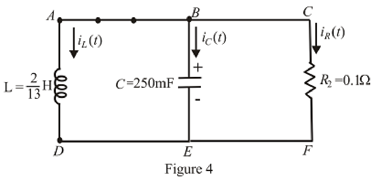
Consider the circuit depicted in Fig. 9.40. (a) Obtain an expression for iL(t) valid for all t > 0. (b) Obtain an expression for iR(t) valid for all t > 0. (c) Determine the settling time for both iL and iR.
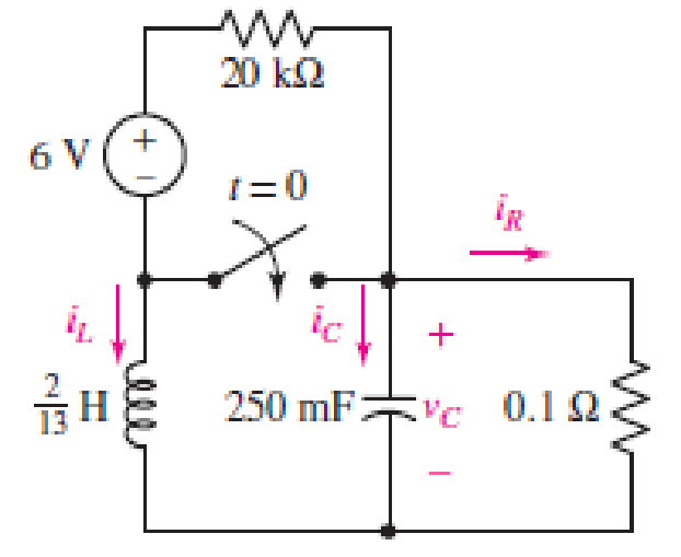
■ FIGURE 9.40
(a)
Obtain an expression for
Answer to Problem 13E
The current across inductor
Explanation of Solution
Formula used:
The expression for the exponential damping coefficient in parallel
Here,
The expression for the resonating frequency in parallel
Here,
The expression for the two solutions of the characteristic equation of a parallel
Here,
The expression for the natural response of the parallel
Here,
Calculation:
The redrawn circuit is shown in Figure 1 as follows:
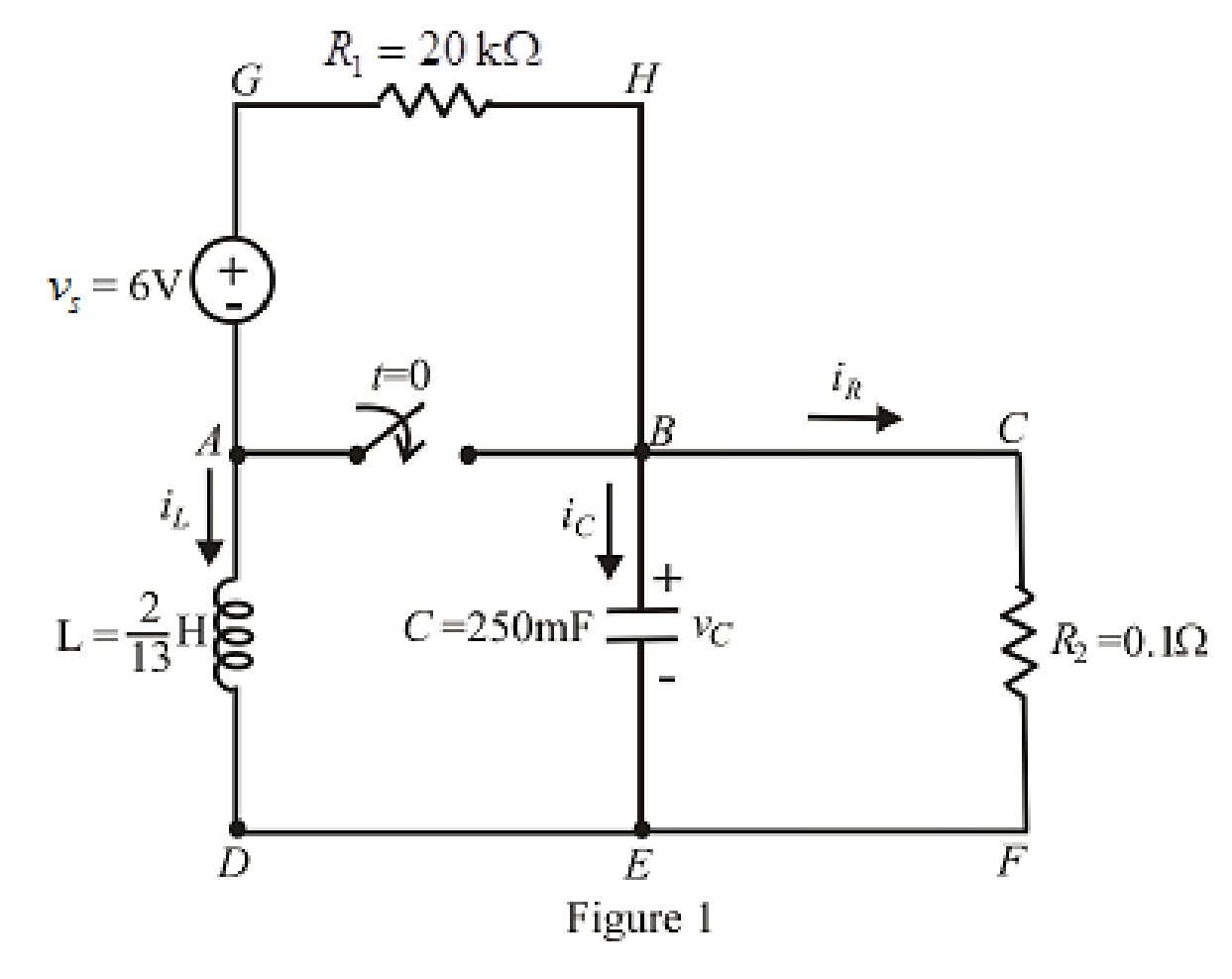
Refer to the Figure 1:
At
Here,
The redrawn circuit at
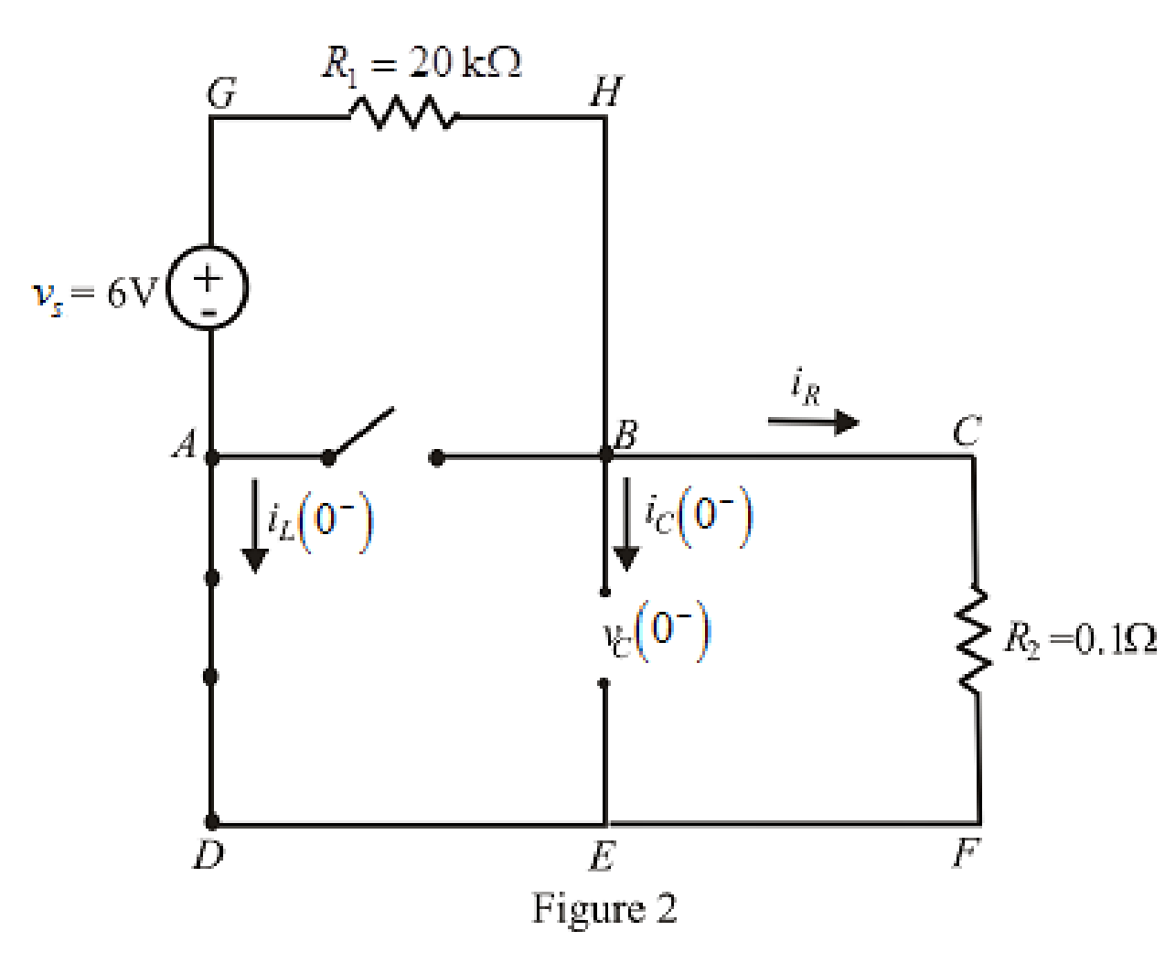
Refer to the Figure 2:
Substitute
The expression for voltage
Here,
Substitute
Substitute
Rearrange for
At
The voltage across inductor is same as voltage across capacitor due to parallel circuit and thus, the expression for voltage across inductor is:
The redrawn circuit is shown in Figure 3 as follows:
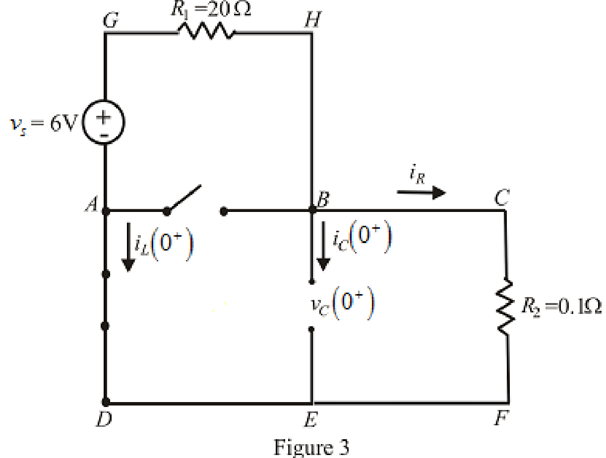
Refer to the Figure 3:
Substitute
Substitute
Differentiate equation (5) both the sides with respect to time
The expression for the voltage across inductor at time
At
Substitute
Rearrange for
Substitute
At
The circuit diagram is redrawn as shown in Figure 4 for
Refer to the redrawn Figure 4:
Substitute
Substitute
As value of exponential frequency
Substitute
Substitute
Substitute
Substitute
Solve for
Rearrange for
Substitute
Rearrange for
Substitute
Conclusion:
Thus, the current across inductor
(b)
Find the equation for current across resistor for
Answer to Problem 13E
The equation of current
Explanation of Solution
Calculation:
Refer to the Figure 3:
The expression for current across resistor at
At
Therefore,
At
Substitute
At
Substitute
Conclusion:
Thus, the equation of current
(c)
Find the settling time for both
Answer to Problem 13E
The settling time for
Explanation of Solution
Calculation:
The settling time is the time at which current reaches to
Since the inductor current is exponential in nature and time cannot be taken as negative, therefore, inductor current takes its maximum value at
Substitute
The maximum value of current is:
The expression for current at settling time
Substitute
The settling time is the time at which the current is decreased to
Equation (24) is solved by scientific calculator which can determine the value of time
Take log both the side in equation (25).
Rearrange for
Substitute
The maximum value of current is:
The expression for current at settling time
Substitute
The settling time is the time at which the current is decreased to
The equation can be approximated for
Take log both the sides of equation (28).
Rearrange for
Conclusion:
Thus, the settling time for
Want to see more full solutions like this?
Chapter 9 Solutions
Loose Leaf for Engineering Circuit Analysis Format: Loose-leaf


- The mathematical models of some continuous time systems are given above. x(t) is the input signal of the system, and y(t) is the output signal of the system. Which of the following systems is linear and which is nonlinear? For linear systems, write "linear" in the space next to the option. For non-linear systems, write "non-linear" in the space next to the option.arrow_forwardA resistor (R = 1 Ω), inductor (L = 0.1 H) and capacitor (C = 0.1 F) are connected in series, and the current I(t) through the circuit is measured as shown in the image below Assuming that the capacitor is uncharged at t = 0, and that the circuit is electrically small (such that propagation times between components can be neglected), find (or approximate where necessary) for times t = [0 : 0.1 : 0.4] (i.e. do not calculate at t = 0.5) : (shown in the image below)arrow_forwardA system has the following characteristic equation: s + s + 3 + 2s + 2 = 0 Using the Routh-Hurwitz method, checkarrow_forward
- The characteristic equation of a system is given as s3+25s2+10s+50=0. What is the number of the roots in the right half s-plane and the imaginary axis respectively?arrow_forwardStep functions can be used to define a window function. Thusu(t −1)−u(t−4) defines a window 1 unit high and 3 units wide located on the time axis between 1 and 4. A function f(t) is defined as follows: f(t)=0,t≤0;=−20t,0≤t≤1 s= −20,1 s≤t≤2 s=2 cosπ2t,2 s≤t≤4 s;=100−20t,4 s≤t≤5 s=0,5 s≤t<∞. 1. Sketch f(t) over the interval −1 s≤t≤6 s. 2. Use the concept of the window function to write an expression for f(t).arrow_forwardObtain the value of I1, if M=1/√2H, and the circuit is in steady state at t = 0.arrow_forward
- A 1 H choke has a resistance of 50 Ω. This choke is supplied with an a.c. voltage given by e= 141 sin 314 t. Find the expression for the transient component of the current flowing throughthe choke after the voltage is suddenly switched on.arrow_forwardA 50ft transmission line is used for a microwave system. Aportion of the transmission line is found to have an inductanceof 0.5 mH, a capacitance of 1000 uF, 1000Ω resistance and 1uSconductance. Find the characteristic impedance of the trans lineassuming at Low frequency application.arrow_forwardThe voltage pulse applied to the 100 mH inductor shown is 0 for t<0 and is given by the expressionv(t)=20te−10t V for t>0. Also assume i=0 for t≤0.. Find the inductor current as a function of time.arrow_forward
- Suppose an electrical signal generated, y(t) can be modelled as follows where t, is time in second, y(t) is voltage in mv. a) Produce graphs showing the amplitude and phase spectrum of y(t). b) State whether this time-domain signal y(t) is periodical, or non-periodical and justify your answer.arrow_forwardIn the circuit below, it is given that R=3Ω, C=7 F, V1=8 volts, and vC(t) at t=0 is 13 volts. What is the capacitor current iC(t), in amperes, at time t=16 seconds?arrow_forward1.3 A coaxial cylindrical capacitor is to be designed with an effective length of 10 cm. The capacitor is expected to have a capacitance of 100 pF and to operate at 11 kV, 1000 kHz. Determine the required thickness if the required insulating material is Polytetrafluoroethylene (P.T.F.E.), &r= 2.0, Eb = 250 kV/cm. Allow a factor of safety of 4 and take to = 8.85x10⁻¹² F/m.arrow_forward
 Introductory Circuit Analysis (13th Edition)Electrical EngineeringISBN:9780133923605Author:Robert L. BoylestadPublisher:PEARSON
 Delmar's Standard Textbook Of ElectricityElectrical EngineeringISBN:9781337900348Author:Stephen L. HermanPublisher:Cengage Learning
 Programmable Logic ControllersElectrical EngineeringISBN:9780073373843Author:Frank D. PetruzellaPublisher:McGraw-Hill Education
 Fundamentals of Electric CircuitsElectrical EngineeringISBN:9780078028229Author:Charles K Alexander, Matthew SadikuPublisher:McGraw-Hill Education
 Electric Circuits. (11th Edition)Electrical EngineeringISBN:9780134746968Author:James W. Nilsson, Susan RiedelPublisher:PEARSON
 Engineering ElectromagneticsElectrical EngineeringISBN:9780078028151Author:Hayt, William H. (william Hart), Jr, BUCK, John A.Publisher:Mcgraw-hill Education,