
Loose Leaf for Engineering Circuit Analysis Format: Loose-leaf
9th Edition
ISBN: 9781259989452
Author: Hayt
Publisher: Mcgraw Hill Publishers
expand_more
expand_more
format_list_bulleted
Videos
Textbook Question
Chapter 9, Problem 52E
In the series circuit of Fig. 9.53, set R = 1 Ω. (a) Compute α and ω0. (b) If is = 3u(−t) + 2u(t) mA, determine vR(0−), iL(0−), vC(0−), vR(0+), iL(0+), vC(0+), iL(∞), and vC(∞).
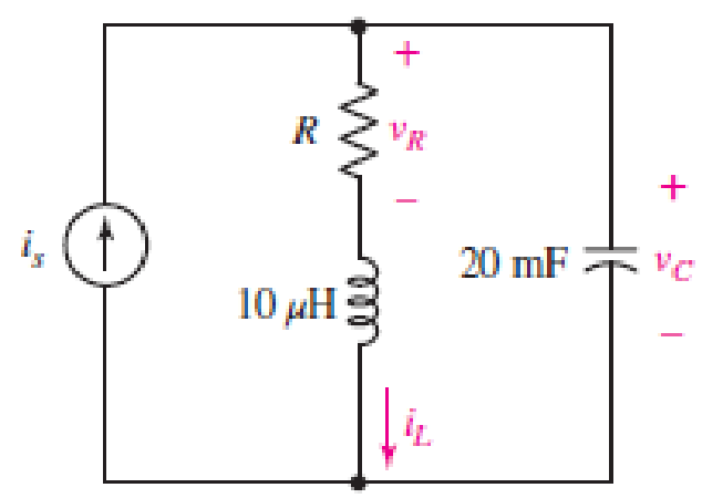
■ FIGURE 9.53
Expert Solution & Answer
Want to see the full answer?
Check out a sample textbook solution
Students have asked these similar questions
identify the following
1. If the pole’s real value is positive and is located on the right side of the S-plane. The system exponentially ____________.2. Is a continuous connection of branches from one node to another with all arrowheads in the same direction.3. Knowing the location of the pole in the S-plane determines the ______________ of the system.
Write an expression for the output voltage for the circuit as shown if υ1 = 0.5 sin 2000πt, and υ2 is generated by the circuit as shown with υ3 = 0.5 sin 10,000πt? Assume VCC = −VEE = 10 V, IEE = 500 μA, R1 = R3 = 2 kΩ, and R = 10 kΩ.
In the circuit shown , the dc current source is replaced with a sinusoidal source that delivers a current of 1.2cost A. The circuit components are R=1 Ω, C=625 mF, and L=1.6 H. Find the numerical expression for V(s).
Chapter 9 Solutions
Loose Leaf for Engineering Circuit Analysis Format: Loose-leaf
Ch. 9.1 - A parallel RLC circuit contains a 100 2 resistor...Ch. 9.2 - After being open for a long time, the switch in...Ch. 9.2 - Prob. 3PCh. 9.2 - Prob. 4PCh. 9.3 - (a) Choose R1 in the circuit of Fig. 9.14 so that...Ch. 9.4 - Prob. 6PCh. 9.5 - Prob. 7PCh. 9.5 - Prob. 8PCh. 9.6 - Let is = 10u(t) 20u(t) A in Fig. 9.31. Find (a)...Ch. 9.6 - Let vs = 10 + 20u(t) V in the circuit of Fig....
Ch. 9.7 - Alter the capacitor value and voltage source in...Ch. 9 - For a certain source-free parallel RLC circuit, R...Ch. 9 - Element values of 10 mF and 2 nH are employed in...Ch. 9 - If a parallel RLC circuit is constructed from...Ch. 9 - Prob. 4ECh. 9 - You go to construct the circuit in Exercise 1,...Ch. 9 - A parallel RLC circuit has inductance 2 mH and...Ch. 9 - Prob. 7ECh. 9 - A parallel RLC circuit has R = 1 k, L = 50 mH. and...Ch. 9 - Prob. 9ECh. 9 - Prob. 10ECh. 9 - The current flowing through a 5 resistor in a...Ch. 9 - For the circuit of Fig.9.40, obtain an expression...Ch. 9 - Consider the circuit depicted in Fig. 9.40. (a)...Ch. 9 - With regard to the circuit represented in Fig....Ch. 9 - (a) Assuming the passive sign convention, obtain...Ch. 9 - With regard to the circuit presented in Fig. 9.42,...Ch. 9 - Obtain expressions for the current i(t) and...Ch. 9 - FIGURE 9.43 Replace the 14 resistor in the...Ch. 9 - Design a complete source-free parallel RLC circuit...Ch. 9 - For the circuit represented by Fig. 9.44, the two...Ch. 9 - Prob. 21ECh. 9 - Prob. 22ECh. 9 - A critically damped parallel RLC circuit is...Ch. 9 - A source-free parallel RLC circuit has an initial...Ch. 9 - A critically damped parallel RLC circuit is...Ch. 9 - For the circuit of Fig. 9.45, is(t) = 30u(t) mA....Ch. 9 - Prob. 27ECh. 9 - The circuit of Fig. 9.44 is rebuilt such that the...Ch. 9 - Prob. 29ECh. 9 - Prob. 30ECh. 9 - The source-free circuit depicted in Fig. 9.1 is...Ch. 9 - (a) Graph the current i for the circuit described...Ch. 9 - Analyze the circuit described in Exercise 31 to...Ch. 9 - A source-free parallel RLC circuit has capacitance...Ch. 9 - Prob. 35ECh. 9 - Obtain an expression for vL(t), t 0, for the...Ch. 9 - For the circuit of Fig. 9.47, determine (a) the...Ch. 9 - (a) Design a parallel RLC circuit that provides a...Ch. 9 - The circuit depicted in Fig. 9.48 is just barely...Ch. 9 - When constructing the circuit of Fig. 9.48, you...Ch. 9 - The circuit of Fig. 9.22a is constructed with a...Ch. 9 - Prob. 42ECh. 9 - Prob. 43ECh. 9 - The simple three-element series RLC circuit of...Ch. 9 - Prob. 45ECh. 9 - Prob. 46ECh. 9 - Prob. 47ECh. 9 - With reference to the series RLC circuit of Fig....Ch. 9 - Obtain an expression for i1 as labeled in Fig....Ch. 9 - The circuit in Fig. 9.52 has the switch in...Ch. 9 - For the circuit in Fig. 9.52, determine the value...Ch. 9 - In the series circuit of Fig. 9.53, set R = 1 ....Ch. 9 - Evaluate the derivative of each current and...Ch. 9 - Consider the circuit depicted in Fig. 9.55. If...Ch. 9 - Prob. 55ECh. 9 - In the circuit shown in Fig. 9.56, (a) obtain an...Ch. 9 - Prob. 57ECh. 9 - For the circuit represented in Fig. 9.57, (a)...Ch. 9 - FIGURE 9.57 Replace the 1 resistor in Fig. 9.57...Ch. 9 - A circuit has an inductive load of 2 H, a...Ch. 9 - (a) Adjust the value of the 3 resistor in the...Ch. 9 - Determine expressions for vC(t) and iL(t) in Fig....Ch. 9 - The capacitor in the LC circuit in Fig. 9.60 has...Ch. 9 - Suppose that the switch in the circuit in Fig....Ch. 9 - The capacitor in the circuit of Fig. 9.63 is set...Ch. 9 - The physical behavior of automotive suspension...Ch. 9 - A lossless LC circuit can be used to provide...
Knowledge Booster


Learn more about
Need a deep-dive on the concept behind this application? Look no further. Learn more about this topic, electrical-engineering and related others by exploring similar questions and additional content below.Similar questions
- The circuit elements in the circuit L=50 mH, and C=0.2 μF. The initial inductor current is−45 mA and the initial capacitor voltage is 15 V.4. The resistance is increased to 312.5 Ω. Find the expression for v(t) for t≥0.arrow_forwardConsider the given circuit with vi=3V, R1=20K, Rf=50K, R2=10K, R3=20K, C=2μF. Assuming that the capacitor is an open circuit, determine vo.arrow_forwardA resistor of 100 Ω, a coil of 4.50 μH, and a capacitor of 220 pF are in parallel. What is the admittance vector at 6.50 MHz? Provide illustration of the circuit.arrow_forward
- Step functions can be used to define a window function. Thusu(t −1)−u(t−4) defines a window 1 unit high and 3 units wide located on the time axis between 1 and 4. A function f(t) is defined as follows: f(t)=0,t≤0;=−20t,0≤t≤1 s= −20,1 s≤t≤2 s=2 cosπ2t,2 s≤t≤4 s;=100−20t,4 s≤t≤5 s=0,5 s≤t<∞. 1. Sketch f(t) over the interval −1 s≤t≤6 s. 2. Use the concept of the window function to write an expression for f(t).arrow_forwardFor the circuit shown below, the initial conditions are zero, Idc is a current source continuous and switch S is open at t = 0.a)Determine the equivalent impedance to the right of points a and b of the circuit, Z(s).b)Obtain the voltage between points a and b of the circuit in the frequency domain, V(s). Employ the initial and final value properties and calculate the values of v(0) and v(∞).c)Find the expression for v(t). Check that the values of v(0) and v(∞) agree with those calculated in the previous item.d)Obtain currents i1(t) and i2(t).arrow_forwardA series LR circuit has a variable inductor with theinductance L(t) is defined by intervals.Find the current i(t) if the resistance is 0.2 ohms, the voltageapplied is E(t) = 4 volts; knowing that i(0) = 0.arrow_forward
- Calculate the current in an RLC circuit with resistances R=11 ohms, L=0.1 H, and C=10^-2 F that is linked to the source V(t)= 10sin 377t. Assume that the capacitor charge and current are both zero at time t=0.arrow_forwardFor the network shown below, the switch is closed on to position 1 when t = 0 and then moved to position 2 when t = 20 ms. Determine the voltage across the capacitor when t = 30 ms. Also plot the response of this circuit from time, t = 0 to t = 40 ms.arrow_forwardFor the circuit below with the switch closed and then opening at t=0, and R1= 3Ω, R2= 7Ω, C = 0.2H, ig = 8A, vs = 2v, calculate the initial condition. Develop the differential equation for the solution for t > 0. Calculate the current ia(t) for all times.arrow_forward
- The closed-loop transfer function of a system is given by G(s) = 14.145 / (s+5)*(s^2 +0.842s+2.829). Which of the following is true for this system? I. The damping ratio is given by 0.25. II. Its natural frequency is given as 1.682 r/s. III. Exceeding the percentage is given with 44.4%. IV. The peak time is given as 1.93 s. a) I only b) I, II, II and IV c) II and III only d) I, II and IV onlyarrow_forwardA circuit is constructed with an AC generator, a resistor, capacitor and inductor as shown. The generator voltage varies in time as ε =Va - Vb = εmsinωt, where εm = 120 V and ω = 726 radians/second. The values for the remaining circuit components are: R = 62 Ω, L = 95.6 mH, and C = 13.8μF. 4) What is t1, the first time after t = 0 when the voltage across the inductor is zero? 6) What is VC = Vd - Va, the voltage across the capacitor, at time t = 0? Note that VC is a signed number.arrow_forwardThe mathematical models of some continuous time systems are given above. x(t) is the input signal of the system, and y(t) is the output signal of the system. Which of the following systems is linear and which is nonlinear? For linear systems, write "linear" in the space next to the option. For non-linear systems, write "non-linear" in the space next to the option.arrow_forward
arrow_back_ios
SEE MORE QUESTIONS
arrow_forward_ios
Recommended textbooks for you
 Introductory Circuit Analysis (13th Edition)Electrical EngineeringISBN:9780133923605Author:Robert L. BoylestadPublisher:PEARSON
 Delmar's Standard Textbook Of ElectricityElectrical EngineeringISBN:9781337900348Author:Stephen L. HermanPublisher:Cengage Learning
 Programmable Logic ControllersElectrical EngineeringISBN:9780073373843Author:Frank D. PetruzellaPublisher:McGraw-Hill Education
 Fundamentals of Electric CircuitsElectrical EngineeringISBN:9780078028229Author:Charles K Alexander, Matthew SadikuPublisher:McGraw-Hill Education
 Electric Circuits. (11th Edition)Electrical EngineeringISBN:9780134746968Author:James W. Nilsson, Susan RiedelPublisher:PEARSON
 Engineering ElectromagneticsElectrical EngineeringISBN:9780078028151Author:Hayt, William H. (william Hart), Jr, BUCK, John A.Publisher:Mcgraw-hill Education,
Introductory Circuit Analysis (13th Edition)
Electrical Engineering
ISBN:9780133923605
Author:Robert L. Boylestad
Publisher:PEARSON
Delmar's Standard Textbook Of Electricity
Electrical Engineering
ISBN:9781337900348
Author:Stephen L. Herman
Publisher:Cengage Learning
Programmable Logic Controllers
Electrical Engineering
ISBN:9780073373843
Author:Frank D. Petruzella
Publisher:McGraw-Hill Education
Fundamentals of Electric Circuits
Electrical Engineering
ISBN:9780078028229
Author:Charles K Alexander, Matthew Sadiku
Publisher:McGraw-Hill Education
Electric Circuits. (11th Edition)
Electrical Engineering
ISBN:9780134746968
Author:James W. Nilsson, Susan Riedel
Publisher:PEARSON
Engineering Electromagnetics
Electrical Engineering
ISBN:9780078028151
Author:Hayt, William H. (william Hart), Jr, BUCK, John A.
Publisher:Mcgraw-hill Education,
Routh Hurwitz Stability Criterion Basic Worked Example; Author: The Complete Guide to Everything;https://www.youtube.com/watch?v=CzzsR5FT-8U;License: Standard Youtube License