
Loose Leaf for Engineering Circuit Analysis Format: Loose-leaf
9th Edition
ISBN: 9781259989452
Author: Hayt
Publisher: Mcgraw Hill Publishers
expand_more
expand_more
format_list_bulleted
Concept explainers
Videos
Textbook Question
Chapter 9, Problem 63E
The capacitor in the LC circuit in Fig. 9.60 has initial energy of 20 pJ stored at time t = 0, while the inductor has no energy stored at t = 0. (a) Determine the capacitor voltage and current for the capacitor for t > 0. (b) Graph the energy stored on the capacitor and inductor as a function of time for the range 0 < t < 5 ns.
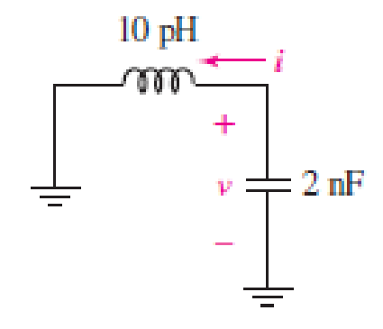
■ FIGURE 9.60
Expert Solution & Answer
Want to see the full answer?
Check out a sample textbook solution
Students have asked these similar questions
Consider the given circuit. The switch has been closed for a very long time before opening at t=0s. Determine the capacitor voltage (in volts) right before the switch has been opened, the time constant of the circuit for t>0 (in ms), and the expression for the capacitor voltage for t≥0.
The voltage pulse applied to the 100 mH inductor shown is 0 for t<0 and is given by the expressionv(t)=20te−10t V for t>0. Also assume i=0 for t≤0.. Find the inductor current as a function of time.
The switch in the circuit has been in position a fora long time. At t=0, the switch moves instantaneously to position band stays there. Find the initial and final values of the capacitorvoltage, the time constant for t≥0, and the expression for thecapacitor voltage for t≥0.
Chapter 9 Solutions
Loose Leaf for Engineering Circuit Analysis Format: Loose-leaf
Ch. 9.1 - A parallel RLC circuit contains a 100 2 resistor...Ch. 9.2 - After being open for a long time, the switch in...Ch. 9.2 - Prob. 3PCh. 9.2 - Prob. 4PCh. 9.3 - (a) Choose R1 in the circuit of Fig. 9.14 so that...Ch. 9.4 - Prob. 6PCh. 9.5 - Prob. 7PCh. 9.5 - Prob. 8PCh. 9.6 - Let is = 10u(t) 20u(t) A in Fig. 9.31. Find (a)...Ch. 9.6 - Let vs = 10 + 20u(t) V in the circuit of Fig....
Ch. 9.7 - Alter the capacitor value and voltage source in...Ch. 9 - For a certain source-free parallel RLC circuit, R...Ch. 9 - Element values of 10 mF and 2 nH are employed in...Ch. 9 - If a parallel RLC circuit is constructed from...Ch. 9 - Prob. 4ECh. 9 - You go to construct the circuit in Exercise 1,...Ch. 9 - A parallel RLC circuit has inductance 2 mH and...Ch. 9 - Prob. 7ECh. 9 - A parallel RLC circuit has R = 1 k, L = 50 mH. and...Ch. 9 - Prob. 9ECh. 9 - Prob. 10ECh. 9 - The current flowing through a 5 resistor in a...Ch. 9 - For the circuit of Fig.9.40, obtain an expression...Ch. 9 - Consider the circuit depicted in Fig. 9.40. (a)...Ch. 9 - With regard to the circuit represented in Fig....Ch. 9 - (a) Assuming the passive sign convention, obtain...Ch. 9 - With regard to the circuit presented in Fig. 9.42,...Ch. 9 - Obtain expressions for the current i(t) and...Ch. 9 - FIGURE 9.43 Replace the 14 resistor in the...Ch. 9 - Design a complete source-free parallel RLC circuit...Ch. 9 - For the circuit represented by Fig. 9.44, the two...Ch. 9 - Prob. 21ECh. 9 - Prob. 22ECh. 9 - A critically damped parallel RLC circuit is...Ch. 9 - A source-free parallel RLC circuit has an initial...Ch. 9 - A critically damped parallel RLC circuit is...Ch. 9 - For the circuit of Fig. 9.45, is(t) = 30u(t) mA....Ch. 9 - Prob. 27ECh. 9 - The circuit of Fig. 9.44 is rebuilt such that the...Ch. 9 - Prob. 29ECh. 9 - Prob. 30ECh. 9 - The source-free circuit depicted in Fig. 9.1 is...Ch. 9 - (a) Graph the current i for the circuit described...Ch. 9 - Analyze the circuit described in Exercise 31 to...Ch. 9 - A source-free parallel RLC circuit has capacitance...Ch. 9 - Prob. 35ECh. 9 - Obtain an expression for vL(t), t 0, for the...Ch. 9 - For the circuit of Fig. 9.47, determine (a) the...Ch. 9 - (a) Design a parallel RLC circuit that provides a...Ch. 9 - The circuit depicted in Fig. 9.48 is just barely...Ch. 9 - When constructing the circuit of Fig. 9.48, you...Ch. 9 - The circuit of Fig. 9.22a is constructed with a...Ch. 9 - Prob. 42ECh. 9 - Prob. 43ECh. 9 - The simple three-element series RLC circuit of...Ch. 9 - Prob. 45ECh. 9 - Prob. 46ECh. 9 - Prob. 47ECh. 9 - With reference to the series RLC circuit of Fig....Ch. 9 - Obtain an expression for i1 as labeled in Fig....Ch. 9 - The circuit in Fig. 9.52 has the switch in...Ch. 9 - For the circuit in Fig. 9.52, determine the value...Ch. 9 - In the series circuit of Fig. 9.53, set R = 1 ....Ch. 9 - Evaluate the derivative of each current and...Ch. 9 - Consider the circuit depicted in Fig. 9.55. If...Ch. 9 - Prob. 55ECh. 9 - In the circuit shown in Fig. 9.56, (a) obtain an...Ch. 9 - Prob. 57ECh. 9 - For the circuit represented in Fig. 9.57, (a)...Ch. 9 - FIGURE 9.57 Replace the 1 resistor in Fig. 9.57...Ch. 9 - A circuit has an inductive load of 2 H, a...Ch. 9 - (a) Adjust the value of the 3 resistor in the...Ch. 9 - Determine expressions for vC(t) and iL(t) in Fig....Ch. 9 - The capacitor in the LC circuit in Fig. 9.60 has...Ch. 9 - Suppose that the switch in the circuit in Fig....Ch. 9 - The capacitor in the circuit of Fig. 9.63 is set...Ch. 9 - The physical behavior of automotive suspension...Ch. 9 - A lossless LC circuit can be used to provide...
Knowledge Booster


Learn more about
Need a deep-dive on the concept behind this application? Look no further. Learn more about this topic, electrical-engineering and related others by exploring similar questions and additional content below.Similar questions
- The voltage pulse applied to the 100 mH inductor shown is 0 for t<0. and is given by the expression v(t)=20te−10t V for t>0. Also assume i=0 for t≤0. Sketch the voltage as a function of time.arrow_forwardWhen a capacitor holding an initial electrical charge of 60 microcoulombs (µC) is discharged through an electrical circuit, the remaining charge on the capacitor is q(t) = 60e-t/4 , where t is time elapsed in seconds. (a) Find q'(t), the electrical current in the circuit, as a function of t. (b) When is the magnitude of the electrical current in the circuit the greatest, and what is its value at this time?arrow_forwardAll capacitors were initially discharged. at t = 0, S1 is placed at position 1 and S2 is closed. During this phase, it has been determined that Eth and Rth seen by the equivalent capacitor are, respectively, 20 V and 6.0 kΩ. The time constant is 29 ms. At t = 15 ms, S1 is placed at position 2 and S2 is kept closed. Calculate the equivalent capacitor voltage vT at t = 15 ms. Enter your answer in V rounded to 2 decimal places. At t = 25 ms, S1 is kept at position 2 and S2 is opened. Data: R1 = 5 kΩ, R2 = 3 kΩ, R4 = 2 kΩ, R5 = 20 kΩ, R6 = 12.0 kΩ;arrow_forward
- Let Vs=530tᶾ v, leg t >0 and iL (0) = 1 A, in the circuit shown, at t=0.2s, determine the values of the energy stored in the capacitor and the coil. The circuit is in the attached image.arrow_forwardThe initial condition current of the inductance is given as iL(0)=1A. circuitBy analyzing the domain of s, we can find the intrinsic solution, forced solution, and exact solution of the current iL(t).find.Element values R1=R2=R3=1Ω, e(t)=Cos 3t Volts,It is L=β H. α=7,β=4arrow_forwardThe resistance, inductance, and capacitance in a parallel RLC circuitare 1 kΩ, 12.5 H, and 2 μF, respectively.1. Calculate the roots of the characteristic equation that describe thevoltage response of the circuit.2. Will the response be over-, under-, or critically damped?3. What value of R will yield a damped frequency of 120 rad/s?4. What are the roots of the characteristic equation for the value of Rfound in (c)?5. What value of R will result in a critically damped response?arrow_forward
- Consider the RLC circuit shown where the initial current flowing through the circuit at time t = 0 is I_0 = 5 and the initial charge on the capacitor at time t = 0 is Q_0 = 2. The components have values of R = 100 ohms, L = 5 H, and C = 1/450,500 F. Write the differential equation for Q(t), the charge across the capacitor, assuming the voltage source V(t) = 0arrow_forwardThe equation for the voltage ?(?) across a capacitor at time ? is?(?)=1?(∫?(?)???0+?0)Where ?(?) is the current passing through the capacitor, and ?0 is the initial charge. Consider a capacitor with ?=1?? and ?0=0. If ?(?)=0.1(0.2+sin0.5?) A, find ?(?) for ?=0.5 sec.arrow_forwardConsider the circuit above. The switch has been closed for a very long time before opening at t=0s. Determine the Inductor current (in amperes) right after the switch has been opened, the time constant of the circuit for ?>0 (in ms), and the Expression for the inductor current for ?≥0.arrow_forward
- Derive the expression for heart ratein beats per minute given the values of R and C and assuming that thecapacitor discharges when its voltage reaches 75% of the source voltageVs. The expression, given in the Practical Perspective, is repeated herefor convenience:H=60−RC ln 0.25 [beats per minute].arrow_forwardThe circuit elements in the circuit L=50 mH, and C=0.2 μF. The initial inductor current is−45 mA and the initial capacitor voltage is 15 V. The resistance is increased to250 Ω. Find the expression for v(t) for t≥0.arrow_forwardThe circuit shown below is an underdamped system, and the current through the inductor has the form iL(t)=e^at ( ) (K1sinwt + K2coswt ) for t≥0 a. Determine the numerical values, including signs, of a and w b. If the initial conditions are iL(0) = 1A and Vc (0) =12V , determine the numerical values, including signs, of K1 and K2 c. Using the numbers determined above, write out the complete expression for iL(t)arrow_forward
arrow_back_ios
SEE MORE QUESTIONS
arrow_forward_ios
Recommended textbooks for you
 Introductory Circuit Analysis (13th Edition)Electrical EngineeringISBN:9780133923605Author:Robert L. BoylestadPublisher:PEARSON
 Delmar's Standard Textbook Of ElectricityElectrical EngineeringISBN:9781337900348Author:Stephen L. HermanPublisher:Cengage Learning
 Programmable Logic ControllersElectrical EngineeringISBN:9780073373843Author:Frank D. PetruzellaPublisher:McGraw-Hill Education
 Fundamentals of Electric CircuitsElectrical EngineeringISBN:9780078028229Author:Charles K Alexander, Matthew SadikuPublisher:McGraw-Hill Education
 Electric Circuits. (11th Edition)Electrical EngineeringISBN:9780134746968Author:James W. Nilsson, Susan RiedelPublisher:PEARSON
 Engineering ElectromagneticsElectrical EngineeringISBN:9780078028151Author:Hayt, William H. (william Hart), Jr, BUCK, John A.Publisher:Mcgraw-hill Education,
Introductory Circuit Analysis (13th Edition)
Electrical Engineering
ISBN:9780133923605
Author:Robert L. Boylestad
Publisher:PEARSON
Delmar's Standard Textbook Of Electricity
Electrical Engineering
ISBN:9781337900348
Author:Stephen L. Herman
Publisher:Cengage Learning
Programmable Logic Controllers
Electrical Engineering
ISBN:9780073373843
Author:Frank D. Petruzella
Publisher:McGraw-Hill Education
Fundamentals of Electric Circuits
Electrical Engineering
ISBN:9780078028229
Author:Charles K Alexander, Matthew Sadiku
Publisher:McGraw-Hill Education
Electric Circuits. (11th Edition)
Electrical Engineering
ISBN:9780134746968
Author:James W. Nilsson, Susan Riedel
Publisher:PEARSON
Engineering Electromagnetics
Electrical Engineering
ISBN:9780078028151
Author:Hayt, William H. (william Hart), Jr, BUCK, John A.
Publisher:Mcgraw-hill Education,
ENA 9.2(1)(En)(Alex) Sinusoids & Phasors - Explanation with Example 9.1 ,9.2 & PP 9.2; Author: Electrical Engineering Academy;https://www.youtube.com/watch?v=vX_LLNl-ZpU;License: Standard YouTube License, CC-BY
Electrical Engineering: Ch 10 Alternating Voltages & Phasors (8 of 82) What is a Phasor?; Author: Michel van Biezen;https://www.youtube.com/watch?v=2I1tF3ixNg0;License: Standard Youtube License