
Videos
The physical behavior of automotive suspension systems is similar to an RLC circuit. The differential equation is defined by
where p(t) is the position variable of a piston in the cylinder of a shock absorber, m is the mass of the wheel, μf is the coefficient of friction, and K is the spring constant. The equivalent circuit representation is shown in Fig. 9.64. Suppose that the suspension is in its initial position at t = 0 (p(0) = 0), but it experiences a bump such that dp/dt at t = 0 is
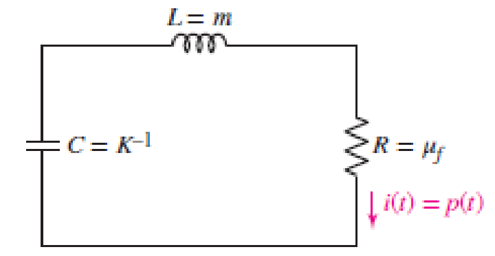
■ FIGURE 9.64
Want to see the full answer?
Check out a sample textbook solution
Chapter 9 Solutions
Loose Leaf for Engineering Circuit Analysis Format: Loose-leaf


- The switch in the circuit shown has been in position a for a long time. At t=0, the switch moves instantaneously to position b. 1. Derive the integrodifferential equation that governs the behavior of the current io for t≥0+. 2. Show that Io(s)=Idc[s+(1/RC)][s2+(1/RC)s+(1/LC)].arrow_forwardThe block diagram of a time-invariant, linear, continuous-time system is given below. X1(s) and X2(s) are the state variables of the system. U(s) is the input signal of the system, Y(s) is the output signal of the system. What is the value of parameter E?arrow_forwardMake the equation s(s+1)(s+2)+K=0 in the form of 1+KF(s) and explain the drawing of root-locus curves. (Note: Indicate the splitting points, centers and angles of the asymptotes)arrow_forward
- Given C(s)/R(s) = 2/ (s+1)(s+6). The system is excited with step input. Obtain the time response, c(t) of the system.arrow_forwardThe switch in the circuit has been closed for a long time before opening at t=0. 1. a) Construct the s-domain equivalent circuit for t>0. 2. b) Find Io. 3. c) Find io for t≥0.arrow_forwardFind and graph the current i(t) in the RLC circuit of the figure, where R=1 Ω, L= 0,25 H, C=0,2 F, v(t)=377sin(20t) V for (10/π) seconds ≤ t ≤ (25/π) seconds, and v(t) = 0 for 0 ≤ t < (10/π) seconds and (25/π) seconds < t < ∞, considering the initial current and load as null. (Note: Use the Laplace method as they are causal systems)arrow_forward
- Plot the step response of the continuous and discrete-time systems:arrow_forward1. Look at the first-order differential equation and answer. y(n)-0.2y(n-1)=x(n), y(-1)=-1 (1) Find out the Impulse response. (2) Find out the general solution when x(n)=r(n)arrow_forwardFor the circuit below determine: a) vc(0+), iL(0+) b) dvc(0+)/dt , vc(∞) c) Is the circuit Underdamped, Critically Damped or Overdamped?d) Determine the expression for the voltage across the capacitor for t > 0.arrow_forward
- The response Y(s) = 4 / (s-1)^3 is most likely a. overdamped b. undamped c underdamped d. critically damped e. nonearrow_forwardThe block diagram of a time-invariant linear continuous time system is given below. G1(s), G2(s) and G3(s) are the transfer functions of subsystems. Determine the stability of the whole system.arrow_forwardThe mathematical models of some continuous time systems are given above. x(t) is the input signal of the system, and y(t) is the output signal of the system. Which of the following systems is linear and which is nonlinear?arrow_forward
 Introductory Circuit Analysis (13th Edition)Electrical EngineeringISBN:9780133923605Author:Robert L. BoylestadPublisher:PEARSON
 Delmar's Standard Textbook Of ElectricityElectrical EngineeringISBN:9781337900348Author:Stephen L. HermanPublisher:Cengage Learning
 Programmable Logic ControllersElectrical EngineeringISBN:9780073373843Author:Frank D. PetruzellaPublisher:McGraw-Hill Education
 Fundamentals of Electric CircuitsElectrical EngineeringISBN:9780078028229Author:Charles K Alexander, Matthew SadikuPublisher:McGraw-Hill Education
 Electric Circuits. (11th Edition)Electrical EngineeringISBN:9780134746968Author:James W. Nilsson, Susan RiedelPublisher:PEARSON
 Engineering ElectromagneticsElectrical EngineeringISBN:9780078028151Author:Hayt, William H. (william Hart), Jr, BUCK, John A.Publisher:Mcgraw-hill Education,