
Concept explainers
Videos
(a) Assuming the passive sign convention, obtain an expression for the voltage across the 1 Ω resistor in the circuit of Fig. 9.41 which is valid for all t > 0. (b) Determine the settling time of the resistor voltage.
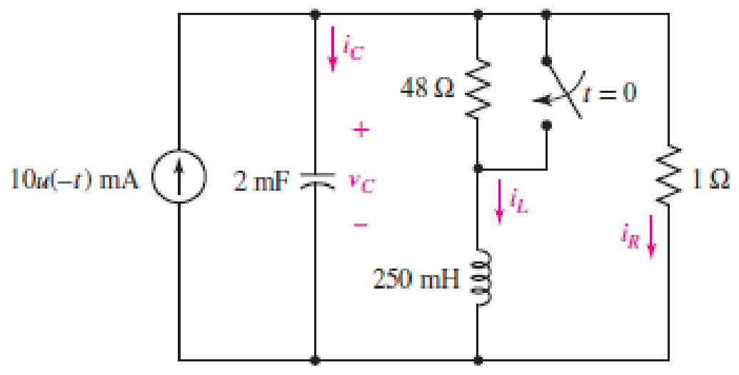
■ FIGURE 9.41
(a)
Obtain an expression for voltage across
Answer to Problem 15E
The expression for voltage across
Explanation of Solution
Formula used:
The expression for the exponential damping coefficient or the neper frequency is as follows:
Here,
The expression for the resonating frequency is as follows:
Here,
The expression for the two solutions of the characteristic equation of a parallel
Here,
The expression for the natural response of the parallel
Here,
Calculation:
The redrawn circuit diagram is given in Figure 1 for
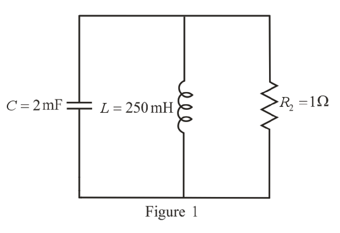
Refer to the redrawn Figure 1:
Substitute
Substitute
As value of neper frequency
Substitute
Substitute
The unit-step forcing function as a function of time which is zero for all values of its argument less than zero and which is unity for all positive values of its argument.
Here,
So, at
The capacitor and the inductor are connected in the circuit for long time.
So, the capacitor behaves as open circuit and the inductor behaves as short circuit.
The redrawn circuit diagram is given in Figure 2 for
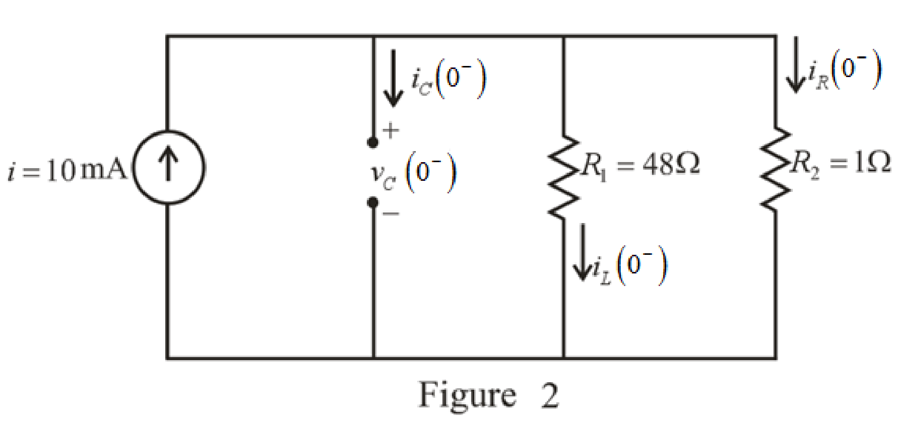
Refer to the redrawn Figure 2:
The expression for the current flowing in the
Here,
Substitute
The expression for the voltage across the
Here,
Substitute
The switch closes at
The capacitor does not allow sudden change in the voltage and the capacitor does not allow sudden change in the current.
So,
As parallel branches have same voltage across them, so, voltage across resistor
Therefore,
The redrawn circuit diagram is given in Figure 3 for
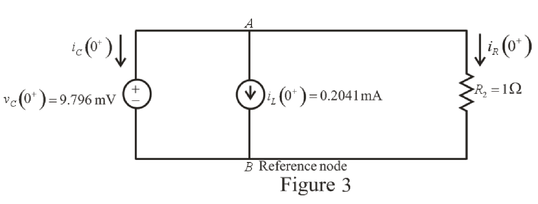
Refer to the redrawn Figure 3:
The expression for the current flowing in the resistor
Here,
Substitute
Apply KCL at node
Here,
Substitute
Rearrange for
Substitute
Substitute
The voltage across the resistor
Substitute
Rearrange for
The expression for the current flowing through the
Substitute
Rearrange for
Substitute
The current flowing through the
Substitute
Rearrange for
Substitute
Rearrange for
Substitute
Substitute
Conclusion:
Thus, expression for voltage across
(b)
Find settling time of the resistor voltage.
Answer to Problem 15E
The settling time is
Explanation of Solution
Calculation:
Function for voltage across resistor
The maximum value of voltage
Substitute
So, the maximum value of voltage
Settling time is the time at which the value of the voltage
The expression for the voltage
Here,
Substitute
Substitute
Since the component
So, the new equation is:
Rearrange equation (20).
Take natural logarithm both sides.
Conclusion:
Thus, the settling time is
Want to see more full solutions like this?
Chapter 9 Solutions
Loose Leaf for Engineering Circuit Analysis Format: Loose-leaf


- If the roots of the characteristic equation are -3,0 then the system is _________________________. Marginally stable Conditionally stable Stable Unstablearrow_forwardA resistance of 100 Ω, an inductance of 0.1 H, and a capacitance of 5(10−5) F are connected in series.If the total electromotive force is given by 110 sin 377t, such that at t = 0,Q = 0, and i = 0, find thecurrent for t > 0.arrow_forwardThe voltage pulse applied to the 100 mH inductor shown is 0 for t<0. and is given by the expression v(t)=20te−10t V for t>0. Also assume i=0 for t≤0. Sketch the voltage as a function of time.arrow_forward
- A current given by i(t)= 3+6 t−−−−−√ (A), where t is measured in seconds, flows through a circuit containing a 14 mF capacitor. Assume the capacitor is initially uncharged. Determine the voltage across the capacitor after 290 ms. Round your answer to 3 significant digits. Value of VC at t= 290 ms is (Volts)arrow_forwardThe following equation is linear, constant-coefficient, homogeneous ordinary differential equation. my′′(t) + Ks y(t) = mg + 30Ks Select one: True Falsearrow_forwardAn inductance of 1 H, a resistance of 8 Ω and capacitance of 0.04 F are connected in series with a variable voltage E = 50 sin 3t. Find the current and charge in the system, given the initial conditions q = 0 and l = 0 when t = 0, using method of solution of higher order linear ordinary differential equation.arrow_forward
- Obtain the value of I1, if M=1/√2H, and the circuit is in steady state at t = 0.arrow_forwardThe initial condition current of the inductance is given as iL(0)=1A. circuitBy analyzing the domain of s, we can find the intrinsic solution, forced solution, and exact solution of the current iL(t).find.Element values R1=R2=R3=1Ω, e(t)=Cos 3t Volts,It is L=β H. α=7,β=4arrow_forwardIn response to a change introduced by a switch at t = 0, the current flowing through a 100 μF capacitor, defined in accordance with the passive sign convention, was observed to be i(t) = −0.4e−0.5t mA (for t > 0). If the final energy stored in the capacitor (at t = ∞) is 0.2 mJ, determine υ(t) for t ≥ 0.arrow_forward
- 1. Find the outer radius of a coaxial cable having a characteristic impedance of 12 and a dielectric constant of 0.06. The outer inner radius of this cable is 4 cm. 2. How much is the inductance of a coil of an instrument that induces 1000 V when its current changes at the rate of 50 mA in 2 µsarrow_forwardA 1 H choke has a resistance of 50 Ω. This choke is supplied with an a.c. voltage given by e= 141 sin 314 t. Find the expression for the transient component of the current flowing throughthe choke after the voltage is suddenly switched on.arrow_forwardconsider the translational mechanical network system a 1lb force f(t), si applied at t=0 if fv=1 find K and M such response is characterized by 4 sec settling time and 1 sec peak time also what is the resulting %OSarrow_forward
 Introductory Circuit Analysis (13th Edition)Electrical EngineeringISBN:9780133923605Author:Robert L. BoylestadPublisher:PEARSON
 Delmar's Standard Textbook Of ElectricityElectrical EngineeringISBN:9781337900348Author:Stephen L. HermanPublisher:Cengage Learning
 Programmable Logic ControllersElectrical EngineeringISBN:9780073373843Author:Frank D. PetruzellaPublisher:McGraw-Hill Education
 Fundamentals of Electric CircuitsElectrical EngineeringISBN:9780078028229Author:Charles K Alexander, Matthew SadikuPublisher:McGraw-Hill Education
 Electric Circuits. (11th Edition)Electrical EngineeringISBN:9780134746968Author:James W. Nilsson, Susan RiedelPublisher:PEARSON
 Engineering ElectromagneticsElectrical EngineeringISBN:9780078028151Author:Hayt, William H. (william Hart), Jr, BUCK, John A.Publisher:Mcgraw-hill Education,