
Loose Leaf for Engineering Circuit Analysis Format: Loose-leaf
9th Edition
ISBN: 9781259989452
Author: Hayt
Publisher: Mcgraw Hill Publishers
expand_more
expand_more
format_list_bulleted
Concept explainers
Videos
Textbook Question
Chapter 9, Problem 32E
(a) Graph the current i for the circuit described in Exercise 31 for resistor values 1.5 kΩ, 15 kΩ, and 150 kΩ. Make three separate graphs, and be sure to extend the corresponding time axis to observe the settling time in each case. (b) Determine the corresponding settling times.
31. The source-free circuit depicted in Fig. 9.1 is constructed using a 10 mH inductor, a 1 mF capacitor, and a 1.5 kΩ resistor. (a) Calculate α, ωd, and ω0. (b) Write the equation which describes the current i for t > 0. (c) Determine the maximum value of i, and the time at which it occurs, if the inductor initially stores no energy and v(0−) = 9 V.
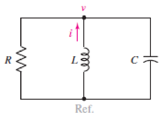
■ FIGURE 9.1 The source-free parallel RLC circuit.
Expert Solution & Answer
Want to see the full answer?
Check out a sample textbook solution
Students have asked these similar questions
The initial condition current of the inductance is given as iL(0)=1A. circuitBy analyzing the domain of s, we can find the intrinsic solution, forced solution, and exact solution of the current iL(t).find.Element values R1=R2=R3=1Ω, e(t)=Cos 3t Volts,It is L=β H.
α=7,β=4
As displayed in attachment figure and LC circuit can be modeled by the following system of differential equations as attachment. Where L = inductance (H), t = time (s), i = current (A), and C = capacitance (F). Assuming that a solution is of the form = Ij sin (wt), determine the eigenvalues and eigenvectors for this system using Faddeev-Leverrier Method and Power Method with L = 1 H and C = 0.25 C. Draw the network, illustrating how the currents oscillate in their primary nodes. Assume initial value for power method.
An inductance of 1 H, a resistance of 8 Ω and capacitance of 0.04 F are connected in series with a variable voltage E = 50 sin 3t. Find the current and charge in the system, given the initial conditions q = 0 and l = 0 when t = 0, using method of solution of higher order linear ordinary differential equation.
Chapter 9 Solutions
Loose Leaf for Engineering Circuit Analysis Format: Loose-leaf
Ch. 9.1 - A parallel RLC circuit contains a 100 2 resistor...Ch. 9.2 - After being open for a long time, the switch in...Ch. 9.2 - Prob. 3PCh. 9.2 - Prob. 4PCh. 9.3 - (a) Choose R1 in the circuit of Fig. 9.14 so that...Ch. 9.4 - Prob. 6PCh. 9.5 - Prob. 7PCh. 9.5 - Prob. 8PCh. 9.6 - Let is = 10u(t) 20u(t) A in Fig. 9.31. Find (a)...Ch. 9.6 - Let vs = 10 + 20u(t) V in the circuit of Fig....
Ch. 9.7 - Alter the capacitor value and voltage source in...Ch. 9 - For a certain source-free parallel RLC circuit, R...Ch. 9 - Element values of 10 mF and 2 nH are employed in...Ch. 9 - If a parallel RLC circuit is constructed from...Ch. 9 - Prob. 4ECh. 9 - You go to construct the circuit in Exercise 1,...Ch. 9 - A parallel RLC circuit has inductance 2 mH and...Ch. 9 - Prob. 7ECh. 9 - A parallel RLC circuit has R = 1 k, L = 50 mH. and...Ch. 9 - Prob. 9ECh. 9 - Prob. 10ECh. 9 - The current flowing through a 5 resistor in a...Ch. 9 - For the circuit of Fig.9.40, obtain an expression...Ch. 9 - Consider the circuit depicted in Fig. 9.40. (a)...Ch. 9 - With regard to the circuit represented in Fig....Ch. 9 - (a) Assuming the passive sign convention, obtain...Ch. 9 - With regard to the circuit presented in Fig. 9.42,...Ch. 9 - Obtain expressions for the current i(t) and...Ch. 9 - FIGURE 9.43 Replace the 14 resistor in the...Ch. 9 - Design a complete source-free parallel RLC circuit...Ch. 9 - For the circuit represented by Fig. 9.44, the two...Ch. 9 - Prob. 21ECh. 9 - Prob. 22ECh. 9 - A critically damped parallel RLC circuit is...Ch. 9 - A source-free parallel RLC circuit has an initial...Ch. 9 - A critically damped parallel RLC circuit is...Ch. 9 - For the circuit of Fig. 9.45, is(t) = 30u(t) mA....Ch. 9 - Prob. 27ECh. 9 - The circuit of Fig. 9.44 is rebuilt such that the...Ch. 9 - Prob. 29ECh. 9 - Prob. 30ECh. 9 - The source-free circuit depicted in Fig. 9.1 is...Ch. 9 - (a) Graph the current i for the circuit described...Ch. 9 - Analyze the circuit described in Exercise 31 to...Ch. 9 - A source-free parallel RLC circuit has capacitance...Ch. 9 - Prob. 35ECh. 9 - Obtain an expression for vL(t), t 0, for the...Ch. 9 - For the circuit of Fig. 9.47, determine (a) the...Ch. 9 - (a) Design a parallel RLC circuit that provides a...Ch. 9 - The circuit depicted in Fig. 9.48 is just barely...Ch. 9 - When constructing the circuit of Fig. 9.48, you...Ch. 9 - The circuit of Fig. 9.22a is constructed with a...Ch. 9 - Prob. 42ECh. 9 - Prob. 43ECh. 9 - The simple three-element series RLC circuit of...Ch. 9 - Prob. 45ECh. 9 - Prob. 46ECh. 9 - Prob. 47ECh. 9 - With reference to the series RLC circuit of Fig....Ch. 9 - Obtain an expression for i1 as labeled in Fig....Ch. 9 - The circuit in Fig. 9.52 has the switch in...Ch. 9 - For the circuit in Fig. 9.52, determine the value...Ch. 9 - In the series circuit of Fig. 9.53, set R = 1 ....Ch. 9 - Evaluate the derivative of each current and...Ch. 9 - Consider the circuit depicted in Fig. 9.55. If...Ch. 9 - Prob. 55ECh. 9 - In the circuit shown in Fig. 9.56, (a) obtain an...Ch. 9 - Prob. 57ECh. 9 - For the circuit represented in Fig. 9.57, (a)...Ch. 9 - FIGURE 9.57 Replace the 1 resistor in Fig. 9.57...Ch. 9 - A circuit has an inductive load of 2 H, a...Ch. 9 - (a) Adjust the value of the 3 resistor in the...Ch. 9 - Determine expressions for vC(t) and iL(t) in Fig....Ch. 9 - The capacitor in the LC circuit in Fig. 9.60 has...Ch. 9 - Suppose that the switch in the circuit in Fig....Ch. 9 - The capacitor in the circuit of Fig. 9.63 is set...Ch. 9 - The physical behavior of automotive suspension...Ch. 9 - A lossless LC circuit can be used to provide...
Knowledge Booster


Learn more about
Need a deep-dive on the concept behind this application? Look no further. Learn more about this topic, electrical-engineering and related others by exploring similar questions and additional content below.Similar questions
- The voltage pulse applied to the 100 mH inductor shown is 0 for t<0. and is given by the expression v(t)=20te−10t V for t>0. Also assume i=0 for t≤0. Sketch the voltage as a function of time.arrow_forwardThe switch in Fig. is moved from A to B att 0 after being at For a long time. This places the two capacitors in series, thus allowing equal and opposite dc voltages to be trapped on the capacitors. (a) Determine v1(0-), v2(0-), and vR(0-). (b) Find v1(0+). v2(0+), and vR(0+). (c) Determine the time constant of VR(t). (d) Find vR(t), t> 0. (e) Find i(t). () Find vi(t) and v2(t) from i(t) and the initial values. (g) Show that the stored energy at t = plus the total energy dissipated in the 20 k resistor is equal to the energy stored in the capacitors at t=0arrow_forwardAll capacitors were initially discharged. at t = 0, S1 is placed at position 1 and S2 is closed. During this phase, it has been determined that Eth and Rth seen by the equivalent capacitor are, respectively, 20 V and 6.0 kΩ. The time constant is 29 ms. At t = 15 ms, S1 is placed at position 2 and S2 is kept closed. Calculate the equivalent capacitor voltage vT at t = 15 ms. Enter your answer in V rounded to 2 decimal places. At t = 25 ms, S1 is kept at position 2 and S2 is opened. Data: R1 = 5 kΩ, R2 = 3 kΩ, R4 = 2 kΩ, R5 = 20 kΩ, R6 = 12.0 kΩ;arrow_forward
- Given the circuit below with the switch closed for a long time, then opening at t=0, and with the values R1=129KΩ, R2=128KΩ, R3=103KΩ, calculate the time constant, τ, for the capacitor voltage solution for at t >0.arrow_forwardThe voltage pulse applied to the 100 mH inductor shown is 0 for t<0 and is given by the expression v(t)=20te−10t V for t>0. Also assume i=0 for t≤0. Sketch the current as a function of time.arrow_forwardThe triangular voltage pulse shown below is applied to a 200 mF capacitor. a) Write the expressions thatdescribe vc(t) in the five time intervals t < 0, 0 ≤ t ≤ 2 , 2 ≤ t ≤ 6, 6 ≤ t ≤ 8, and t > 8. b) Derive theexpressions for the capacitor current, power, and energy for the time intervals in part (a).arrow_forward
- In response to a change introduced by a switch at t = 0, the current flowing through a 100 μF capacitor, defined in accordance with the passive sign convention, was observed to be i(t) = −0.4e−0.5t mA (for t > 0). If the final energy stored in the capacitor (at t = ∞) is 0.2 mJ, determine υ(t) for t ≥ 0.arrow_forwardThe voltage pulse applied to the 100 mH inductor shown is 0 for t<0 and is given by the expressionv(t)=20te−10t V for t>0. Also assume i=0 for t≤0.. Find the inductor current as a function of time.arrow_forwardThe initial values of i1 and i2 in the circuit shown are + 3 A and −5 A, respectively. The voltage at the terminals of the parallel inductors for t≥0 is −30e−5t mV. 1. a) If the parallel inductors are replaced by a single inductor, what is its inductance? 2. b) Find the initial current and its reference direction in the equivalent inductor. 3. c) Use the equivalent inductor to find i(t). 4. d) Find i1(t) and i2(t). Verify that the solutions for i1(t), i2(t), and i(t) satisfy Kirchhoff’s current lawarrow_forward
- A resistor (R = 1 Ω), inductor (L = 0.1 H) and capacitor (C = 0.1 F) are connected in series, and the current I(t) through the circuit is measured as shown in the image below Assuming that the capacitor is uncharged at t = 0, and that the circuit is electrically small (such that propagation times between components can be neglected), find (or approximate where necessary) for times t = [0 : 0.1 : 0.4] (i.e. do not calculate at t = 0.5) : (shown in the image below)arrow_forwardA 20μF capacitor is subjected to a voltage pulse having a duration of 1 s. The pulse is described by the following equations: vc(t)={30t2 V,0≤t≤0.5 s;30(t−1)2 V,0.5 s≤t≤1 s;0elsewhere. Sketch the current pulse that exists in the capacitor during the 1 s interval.arrow_forwardAnswer the questions below:For the circuit given below, compute for the value of ?x (assume the circuit has been turned on).1. If at the terminals x−y a resistor of 10 ? is attached2. If at the terminals x−y an inductor of 1 ? is attached 3. If at the terminals x−y a capacitor of 1 ? is attached 4. If a 4? inductor is shunted with a 1 ? resistor and attached at terminals x−yarrow_forward
arrow_back_ios
SEE MORE QUESTIONS
arrow_forward_ios
Recommended textbooks for you
 Introductory Circuit Analysis (13th Edition)Electrical EngineeringISBN:9780133923605Author:Robert L. BoylestadPublisher:PEARSON
 Delmar's Standard Textbook Of ElectricityElectrical EngineeringISBN:9781337900348Author:Stephen L. HermanPublisher:Cengage Learning
 Programmable Logic ControllersElectrical EngineeringISBN:9780073373843Author:Frank D. PetruzellaPublisher:McGraw-Hill Education
 Fundamentals of Electric CircuitsElectrical EngineeringISBN:9780078028229Author:Charles K Alexander, Matthew SadikuPublisher:McGraw-Hill Education
 Electric Circuits. (11th Edition)Electrical EngineeringISBN:9780134746968Author:James W. Nilsson, Susan RiedelPublisher:PEARSON
 Engineering ElectromagneticsElectrical EngineeringISBN:9780078028151Author:Hayt, William H. (william Hart), Jr, BUCK, John A.Publisher:Mcgraw-hill Education,
Introductory Circuit Analysis (13th Edition)
Electrical Engineering
ISBN:9780133923605
Author:Robert L. Boylestad
Publisher:PEARSON
Delmar's Standard Textbook Of Electricity
Electrical Engineering
ISBN:9781337900348
Author:Stephen L. Herman
Publisher:Cengage Learning
Programmable Logic Controllers
Electrical Engineering
ISBN:9780073373843
Author:Frank D. Petruzella
Publisher:McGraw-Hill Education
Fundamentals of Electric Circuits
Electrical Engineering
ISBN:9780078028229
Author:Charles K Alexander, Matthew Sadiku
Publisher:McGraw-Hill Education
Electric Circuits. (11th Edition)
Electrical Engineering
ISBN:9780134746968
Author:James W. Nilsson, Susan Riedel
Publisher:PEARSON
Engineering Electromagnetics
Electrical Engineering
ISBN:9780078028151
Author:Hayt, William H. (william Hart), Jr, BUCK, John A.
Publisher:Mcgraw-hill Education,
ENA 9.2(1)(En)(Alex) Sinusoids & Phasors - Explanation with Example 9.1 ,9.2 & PP 9.2; Author: Electrical Engineering Academy;https://www.youtube.com/watch?v=vX_LLNl-ZpU;License: Standard YouTube License, CC-BY
Electrical Engineering: Ch 10 Alternating Voltages & Phasors (8 of 82) What is a Phasor?; Author: Michel van Biezen;https://www.youtube.com/watch?v=2I1tF3ixNg0;License: Standard Youtube License