
Loose Leaf for Engineering Circuit Analysis Format: Loose-leaf
9th Edition
ISBN: 9781259989452
Author: Hayt
Publisher: Mcgraw Hill Publishers
expand_more
expand_more
format_list_bulleted
Videos
Textbook Question
Chapter 9, Problem 44E
The simple three-element series RLC circuit of Exercise 42 is constructed with the same component values, but the initial capacitor voltage vC(0−) = 2 V and the initial inductor current i(0−) = 1 mA. (a) Obtain an expression for i(t) valid for all t > 0. (b) Verify your solution with an appropriate SPICE simulation.
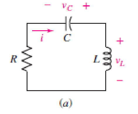
■ FIGURE 9.22(a)
Component values of R = 2 Ω, C = 1 mF, and L = 2 mH are used to construct the circuit represented in Fig. 9.22a. If vC(0−) = 1 V and no current initially flows through the inductor, calculate i(t) at t = 1 ms, 2 ms, and 3 ms.
Expert Solution & Answer
Want to see the full answer?
Check out a sample textbook solution
Students have asked these similar questions
The circuit elements in the circuit L=50 mH, and C=0.2 μF. The initial inductor current is−45 mA and the initial capacitor voltage is 15 V.4. The resistance is increased to 312.5 Ω. Find the expression for v(t) for t≥0.
identify the following
1. If the pole’s real value is positive and is located on the right side of the S-plane. The system exponentially ____________.2. Is a continuous connection of branches from one node to another with all arrowheads in the same direction.3. Knowing the location of the pole in the S-plane determines the ______________ of the system.
In response to a change introduced by a switch at t = 0,
the current flowing through a 100 μF capacitor, defined in
accordance with the passive sign convention, was observed to be
i(t) = −0.4e−0.5t mA (for t > 0).
If the final energy stored in the capacitor (at t = ∞) is 0.2 mJ,
determine υ(t) for t ≥ 0.
Chapter 9 Solutions
Loose Leaf for Engineering Circuit Analysis Format: Loose-leaf
Ch. 9.1 - A parallel RLC circuit contains a 100 2 resistor...Ch. 9.2 - After being open for a long time, the switch in...Ch. 9.2 - Prob. 3PCh. 9.2 - Prob. 4PCh. 9.3 - (a) Choose R1 in the circuit of Fig. 9.14 so that...Ch. 9.4 - Prob. 6PCh. 9.5 - Prob. 7PCh. 9.5 - Prob. 8PCh. 9.6 - Let is = 10u(t) 20u(t) A in Fig. 9.31. Find (a)...Ch. 9.6 - Let vs = 10 + 20u(t) V in the circuit of Fig....
Ch. 9.7 - Alter the capacitor value and voltage source in...Ch. 9 - For a certain source-free parallel RLC circuit, R...Ch. 9 - Element values of 10 mF and 2 nH are employed in...Ch. 9 - If a parallel RLC circuit is constructed from...Ch. 9 - Prob. 4ECh. 9 - You go to construct the circuit in Exercise 1,...Ch. 9 - A parallel RLC circuit has inductance 2 mH and...Ch. 9 - Prob. 7ECh. 9 - A parallel RLC circuit has R = 1 k, L = 50 mH. and...Ch. 9 - Prob. 9ECh. 9 - Prob. 10ECh. 9 - The current flowing through a 5 resistor in a...Ch. 9 - For the circuit of Fig.9.40, obtain an expression...Ch. 9 - Consider the circuit depicted in Fig. 9.40. (a)...Ch. 9 - With regard to the circuit represented in Fig....Ch. 9 - (a) Assuming the passive sign convention, obtain...Ch. 9 - With regard to the circuit presented in Fig. 9.42,...Ch. 9 - Obtain expressions for the current i(t) and...Ch. 9 - FIGURE 9.43 Replace the 14 resistor in the...Ch. 9 - Design a complete source-free parallel RLC circuit...Ch. 9 - For the circuit represented by Fig. 9.44, the two...Ch. 9 - Prob. 21ECh. 9 - Prob. 22ECh. 9 - A critically damped parallel RLC circuit is...Ch. 9 - A source-free parallel RLC circuit has an initial...Ch. 9 - A critically damped parallel RLC circuit is...Ch. 9 - For the circuit of Fig. 9.45, is(t) = 30u(t) mA....Ch. 9 - Prob. 27ECh. 9 - The circuit of Fig. 9.44 is rebuilt such that the...Ch. 9 - Prob. 29ECh. 9 - Prob. 30ECh. 9 - The source-free circuit depicted in Fig. 9.1 is...Ch. 9 - (a) Graph the current i for the circuit described...Ch. 9 - Analyze the circuit described in Exercise 31 to...Ch. 9 - A source-free parallel RLC circuit has capacitance...Ch. 9 - Prob. 35ECh. 9 - Obtain an expression for vL(t), t 0, for the...Ch. 9 - For the circuit of Fig. 9.47, determine (a) the...Ch. 9 - (a) Design a parallel RLC circuit that provides a...Ch. 9 - The circuit depicted in Fig. 9.48 is just barely...Ch. 9 - When constructing the circuit of Fig. 9.48, you...Ch. 9 - The circuit of Fig. 9.22a is constructed with a...Ch. 9 - Prob. 42ECh. 9 - Prob. 43ECh. 9 - The simple three-element series RLC circuit of...Ch. 9 - Prob. 45ECh. 9 - Prob. 46ECh. 9 - Prob. 47ECh. 9 - With reference to the series RLC circuit of Fig....Ch. 9 - Obtain an expression for i1 as labeled in Fig....Ch. 9 - The circuit in Fig. 9.52 has the switch in...Ch. 9 - For the circuit in Fig. 9.52, determine the value...Ch. 9 - In the series circuit of Fig. 9.53, set R = 1 ....Ch. 9 - Evaluate the derivative of each current and...Ch. 9 - Consider the circuit depicted in Fig. 9.55. If...Ch. 9 - Prob. 55ECh. 9 - In the circuit shown in Fig. 9.56, (a) obtain an...Ch. 9 - Prob. 57ECh. 9 - For the circuit represented in Fig. 9.57, (a)...Ch. 9 - FIGURE 9.57 Replace the 1 resistor in Fig. 9.57...Ch. 9 - A circuit has an inductive load of 2 H, a...Ch. 9 - (a) Adjust the value of the 3 resistor in the...Ch. 9 - Determine expressions for vC(t) and iL(t) in Fig....Ch. 9 - The capacitor in the LC circuit in Fig. 9.60 has...Ch. 9 - Suppose that the switch in the circuit in Fig....Ch. 9 - The capacitor in the circuit of Fig. 9.63 is set...Ch. 9 - The physical behavior of automotive suspension...Ch. 9 - A lossless LC circuit can be used to provide...
Knowledge Booster


Learn more about
Need a deep-dive on the concept behind this application? Look no further. Learn more about this topic, electrical-engineering and related others by exploring similar questions and additional content below.Similar questions
- Using the diagram capacitor circuit and values provided, find ZC1, Z T, i, VR1, and Vc1arrow_forwardIf the roots of the characteristic equation are -3,0 then the system is _________________________. Marginally stable Conditionally stable Stable Unstablearrow_forwardThe initial condition current of the inductance is given as iL(0)=1A. circuitBy analyzing the domain of s, we can find the intrinsic solution, forced solution, and exact solution of the current iL(t).find.Element values R1=R2=R3=1Ω, e(t)=Cos 3t Volts,It is L=β H. α=7,β=4arrow_forward
- The current in a 20 mH inductor is known to be i=40 mA,t≤0; i=A1e−10,000t+A2e−40.000tA,t≥0. The voltage across the inductor (passive sign convention) is 28 V at t=0. 1. Find the expression for the voltage across the inductor for t>0. 2. Find the time, greater than zero, when the power at the terminals of the inductor is zero.arrow_forwardA resistance of 100 Ω, an inductance of 0.1 H, and a capacitance of 5(10−5) F are connected in series.If the total electromotive force is given by 110 sin 377t, such that at t = 0,Q = 0, and i = 0, find thecurrent for t > 0.arrow_forwardThe voltage pulse applied to the 100 mH inductor shown is 0 for t<0. and is given by the expression v(t)=20te−10t V for t>0. Also assume i=0 for t≤0. Sketch the voltage as a function of time.arrow_forward
- 2. 7.22 The switch in the circuit has been in the left positionfor a long time. At t=0 it moves to the right position and stays there. 1. a) Write the expression for the capacitor voltage, v(t), for t≥0arrow_forwardThe current flowing through a 10-μF capacitor having terminals labeled a and b is i ab =0.3 exp( −2000t ) Afor t≥0 Given that v ab ( 0 )=0, find an expression for v ab (t) for t≥0. Then,find the energy stored in the capacitor for t=∞..arrow_forwardCan you please help with this question? The triangular voltage pulse shown below is applied to a 200 mF capacitor. a) Write the expressions thatdescribe vc(t) in the five time intervals t < 0, 0 ≤ t ≤ 2 , 2 ≤ t ≤ 6, 6 ≤ t ≤ 8, and t > 8. b) Derive theexpressions for the capacitor current, power, and energy for the time intervals in part (a).arrow_forward
- As displayed in attachment figure and LC circuit can be modeled by the following system of differential equations as attachment. Where L = inductance (H), t = time (s), i = current (A), and C = capacitance (F). Assuming that a solution is of the form = Ij sin (wt), determine the eigenvalues and eigenvectors for this system using Faddeev-Leverrier Method and Power Method with L = 1 H and C = 0.25 C. Draw the network, illustrating how the currents oscillate in their primary nodes. Assume initial value for power method.arrow_forwardThe voltage pulse applied to the 100 mH inductor shown is 0 for t<0 and is given by the expression v(t)=20te−10t V for t>0. Also assume i=0 for t≤0. Sketch the current as a function of time.arrow_forwardThe triangular voltage pulse shown below is applied to a 200 mF capacitor. a) Write the expressions thatdescribe vc(t) in the five time intervals t < 0, 0 ≤ t ≤ 2 , 2 ≤ t ≤ 6, 6 ≤ t ≤ 8, and t > 8. b) Derive theexpressions for the capacitor current, power, and energy for the time intervals in part (a).arrow_forward
arrow_back_ios
SEE MORE QUESTIONS
arrow_forward_ios
Recommended textbooks for you
 Introductory Circuit Analysis (13th Edition)Electrical EngineeringISBN:9780133923605Author:Robert L. BoylestadPublisher:PEARSON
 Delmar's Standard Textbook Of ElectricityElectrical EngineeringISBN:9781337900348Author:Stephen L. HermanPublisher:Cengage Learning
 Programmable Logic ControllersElectrical EngineeringISBN:9780073373843Author:Frank D. PetruzellaPublisher:McGraw-Hill Education
 Fundamentals of Electric CircuitsElectrical EngineeringISBN:9780078028229Author:Charles K Alexander, Matthew SadikuPublisher:McGraw-Hill Education
 Electric Circuits. (11th Edition)Electrical EngineeringISBN:9780134746968Author:James W. Nilsson, Susan RiedelPublisher:PEARSON
 Engineering ElectromagneticsElectrical EngineeringISBN:9780078028151Author:Hayt, William H. (william Hart), Jr, BUCK, John A.Publisher:Mcgraw-hill Education,
Introductory Circuit Analysis (13th Edition)
Electrical Engineering
ISBN:9780133923605
Author:Robert L. Boylestad
Publisher:PEARSON
Delmar's Standard Textbook Of Electricity
Electrical Engineering
ISBN:9781337900348
Author:Stephen L. Herman
Publisher:Cengage Learning
Programmable Logic Controllers
Electrical Engineering
ISBN:9780073373843
Author:Frank D. Petruzella
Publisher:McGraw-Hill Education
Fundamentals of Electric Circuits
Electrical Engineering
ISBN:9780078028229
Author:Charles K Alexander, Matthew Sadiku
Publisher:McGraw-Hill Education
Electric Circuits. (11th Edition)
Electrical Engineering
ISBN:9780134746968
Author:James W. Nilsson, Susan Riedel
Publisher:PEARSON
Engineering Electromagnetics
Electrical Engineering
ISBN:9780078028151
Author:Hayt, William H. (william Hart), Jr, BUCK, John A.
Publisher:Mcgraw-hill Education,
02 - Sinusoidal AC Voltage Sources in Circuits, Part 1; Author: Math and Science;https://www.youtube.com/watch?v=8zMiIHVMfaw;License: Standard Youtube License