
Concept explainers
Videos
For the circuit represented by Fig. 9.44, the two resistor values are R1 = 0.752 Ω and R2 = 1.268 Ω, respectively. (a) Obtain an expression for the energy stored in the capacitor, valid for all t > 0; (b) determine the settling time of the current labeled iA.
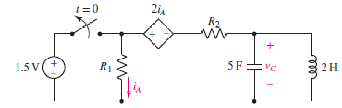
FIGURE 9.44
(a)
Find the expression for the energy stored in the capacitor, valid for all
Answer to Problem 20E
The expression for the energy stored in the capacitor, valid for all
Explanation of Solution
Given Data:
The value of the resistor
Formula used:
The expression for the exponential damping coefficient or the neper frequency is as follows:
Here,
The expression for the resonating frequency is as follows:
Here,
The expression for the two solutions of the characteristic equation of a parallel
Here,
The expression for the natural response of the parallel
Here,
The expression for the energy stored in the capacitor is as follows:
Here,
Calculation:
The capacitor and the inductor are connected in the circuit for long time.
So, the capacitor behaves as open circuit and the inductor behaves as short circuit.
The redrawn circuit diagram is given in Figure 1 for
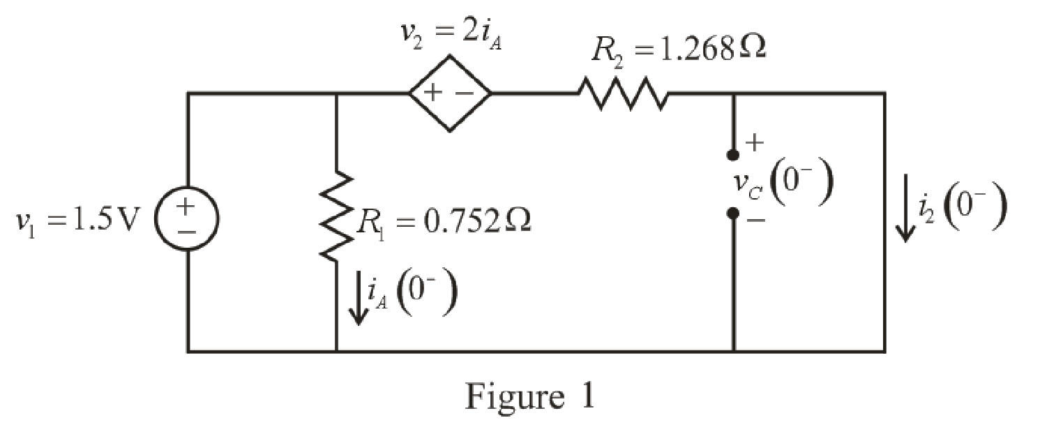
Refer to the redrawn Figure 1:
As parallel branches have same voltage so voltage across
The expression for the current flowing through
Here,
Substitute
The expression for the current flowing through the
Here,
Substitute
Substitute
As parallel branches have same voltage and the voltage across the short circuit branch has
The capacitor does not allow sudden change in the voltage and the inductor does not allow sudden change in current.
So,
Therefore, the voltage across the
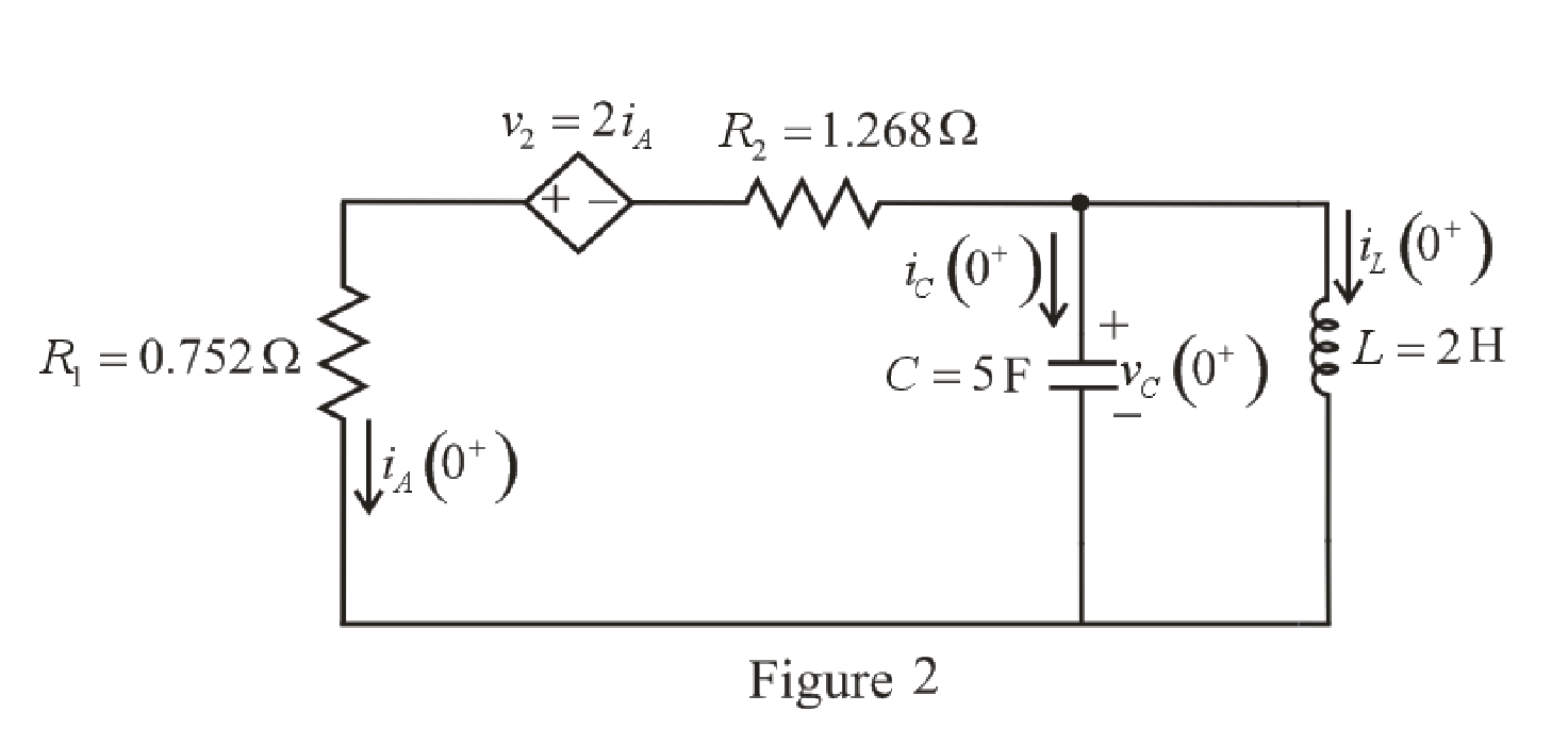
The redrawn circuit diagram is given in Figure 2 at
 l
l
Refer to the redrawn Figure 2:
As the voltage across the he
To find equivalent resistance across the capacitor, a
The redrawn circuit diagram is given in Figure 3.
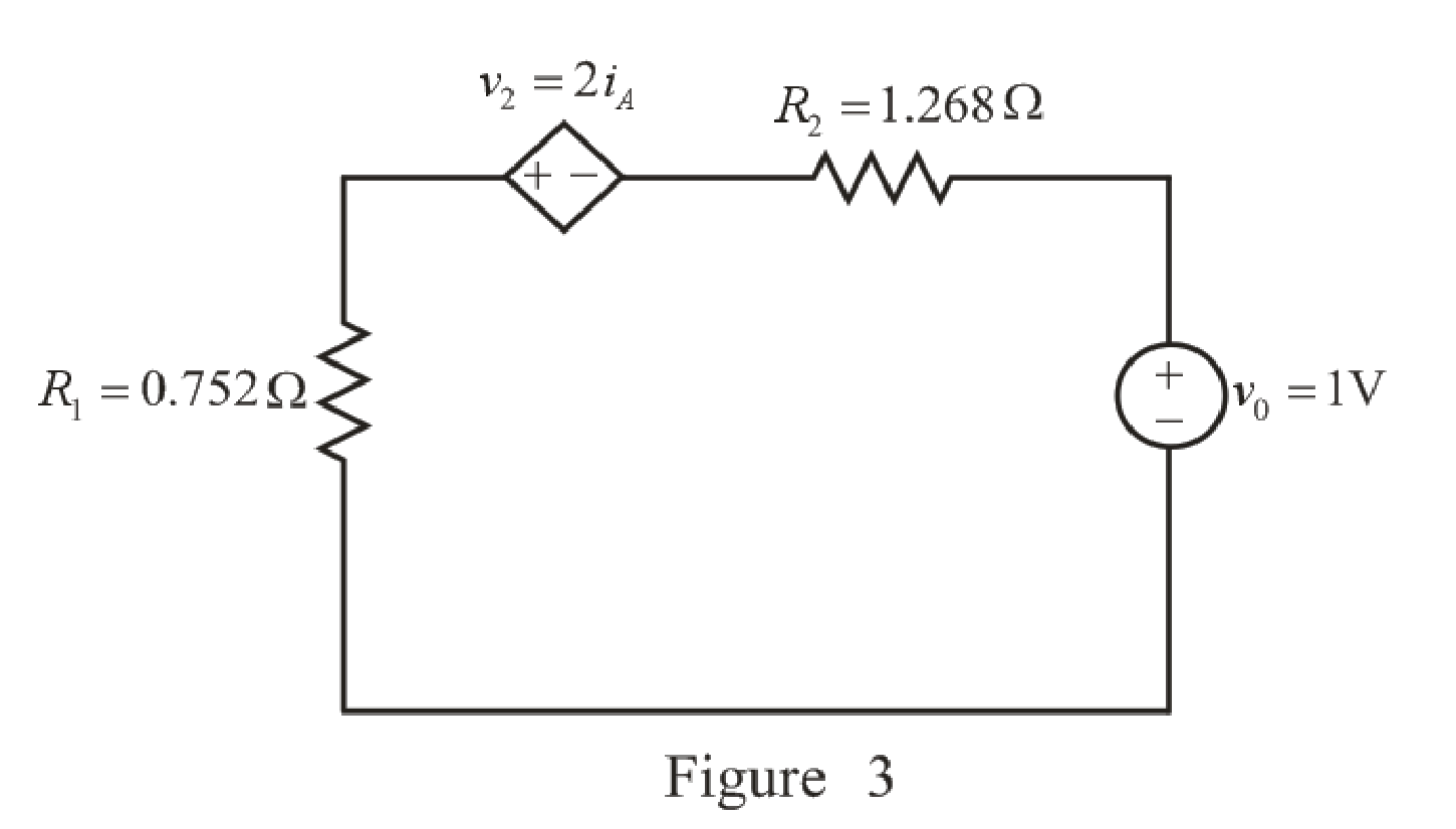
Refer to the redrawn Figure 3:
Apply KVL in the circuit.
Here,
Substitute
Rearrange for
The expression for the equivalent resistance the circuit is as follows:
Here,
Substitute
Substitute
Substitute
Here, the exponential damping coefficient is greater than the resonating frequency,
So, the response of the parallel
Substitute
Substitute
Substitute
Substitute
The voltage across the capacitor at
Substitute
Rearrange for
The expression for the current flowing through the
Substitute
Rearrange for
Substitute
The current flowing through the
Substitute
Rearrange for
Substitute
Rearrange for
Substitute
Substitute
Substitute
So, the energy stored in the capacitor, valid for all
Conclusion:
Thus, the expression for the energy stored in the capacitor, valid for all
(b)
Find the settling time of the current
Answer to Problem 20E
The settling time of current
Explanation of Solution
Calculation:
The redrawn circuit diagram is given in Figure 4.
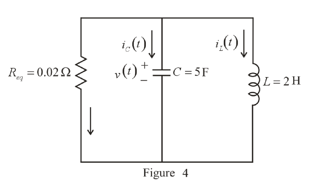
Refer to the redrawn Figure 4:
The expression for the current flowing in the left hand mesh at
Here,
Substitute
Differentiate both side of the equation (19).
The maximum value is obtained when derivative is equated to zero.
Rearrange equation (20).
Take natural logarithm both sides.
Rearrange for
Substitute
So, the value of the maximum current flowing in the left hand mesh is
Settling time is the time at which the value of the current reaches
The expression for the current at
Here,
Substitute
The value of current flowing in the left hand mesh at
Substitute
Since the component
So, the new equation is:
Rearrange equation (22).
Take natural logarithm both sides.
Rearrange for
So, the settling time of the currentflowing in the left hand mesh
Conclusion:
Thus, the settling time of current
Want to see more full solutions like this?
Chapter 9 Solutions
Loose Leaf for Engineering Circuit Analysis Format: Loose-leaf


- 27. A phasor can be represented or expressed in either rectangular form (x +j y) or polar form (z cis n) True False 28. By convention, values obtain from time domain representation are always real while in phasor domain representation, values are generally expressed in complex form. True False 31. Value of capacitance is usually affected by the following physical dimensions and construction of a capacitor: such as number of turns, its length, its cross-sectional area and the permeability of the core. True Falsearrow_forwardThe current in the 20 mH inductor is 10 cos(10,000t + 30°)mA.Calculate (a) the inductive reactance; (b) the impedance of the inductor;(c) the phasor voltage V; and (d) the steady-state expression for v(t)arrow_forward1.3 A coaxial cylindrical capacitor is to be designed with an effective length of 10 cm. The capacitor is expected to have a capacitance of 100 pF and to operate at 11 kV, 1000 kHz. Determine the required thickness if the required insulating material is Polytetrafluoroethylene (P.T.F.E.), &r= 2.0, Eb = 250 kV/cm. Allow a factor of safety of 4 and take to = 8.85x10⁻¹² F/m.arrow_forward
- identify the following 1. If the pole’s real value is positive and is located on the right side of the S-plane. The system exponentially ____________.2. Is a continuous connection of branches from one node to another with all arrowheads in the same direction.3. Knowing the location of the pole in the S-plane determines the ______________ of the system.arrow_forwardCalculate initial conditions for inductor current and capacitor voltage in circuit presented in Fig. 8.3. Assume: L=1H, C=0.5F, R=1Ω, e(t) = 10 2 sin(t + 45 ) V, i(t) = 2sin(t − 45 ) A.arrow_forwardA resistance of 100 Ω, an inductance of 0.1 H, and a capacitance of 5(10−5) F are connected in series.If the total electromotive force is given by 110 sin 377t, such that at t = 0,Q = 0, and i = 0, find thecurrent for t > 0.arrow_forward
- The circuit elements in the circuit L=50 mH, and C=0.2 μF. The initial inductor current is−45 mA and the initial capacitor voltage is 15 V.4. The resistance is increased to 312.5 Ω. Find the expression for v(t) for t≥0.arrow_forwardThe current in a 20 mH inductor is known to be i=40 mA,t≤0; i=A1e−10,000t+A2e−40.000tA,t≥0. The voltage across the inductor (passive sign convention) is 28 V at t=0. 1. Find the expression for the voltage across the inductor for t>0. 2. Find the time, greater than zero, when the power at the terminals of the inductor is zero.arrow_forwardA 20μF capacitor is subjected to a voltage pulse having a duration of 1 s. The pulse is described by the following equations: vc(t)={30t2 V,0≤t≤0.5 s;30(t−1)2 V,0.5 s≤t≤1 s;0elsewhere. Sketch the current pulse that exists in the capacitor during the 1 s interval.arrow_forward
- COURSE: Electrical EngineeringSUBJECT: Electrical ApparatusINSTRUCTIONS:• Write the GIVEN with their respective symbols and units.• Do not skip the SOLUTIONS, do it step-by-step with their respective symbols and units• Round up to 3 three decimal places the FINAL ANSWERS and BOX it. PROBLEM:A capacitor in series with a 66 Ω resistor is connected to a 120 V, 60 Hz source. If the impedance of the circuit is 116 Ω, determine the size of the capacitor.arrow_forwardAll capacitors were initially discharged. at t = 0, S1 is placed at position 1 and S2 is closed. During this phase, it has been determined that Eth and Rth seen by the equivalent capacitor are, respectively, 20 V and 6.0 kΩ. The time constant is 29 ms. At t = 15 ms, S1 is placed at position 2 and S2 is kept closed. Calculate the equivalent capacitor voltage vT at t = 15 ms. Enter your answer in V rounded to 2 decimal places. At t = 25 ms, S1 is kept at position 2 and S2 is opened. Data: R1 = 5 kΩ, R2 = 3 kΩ, R4 = 2 kΩ, R5 = 20 kΩ, R6 = 12.0 kΩ;arrow_forwardAn electrical circuit has a very small resistance so it can be despised. The capacitor on the left was charged up to the voltage of Vo=10 volts and then, at time t=0, the switch S was closed. The capacity of the capacitors are C=60 µF, and the coil inductance is L=0.04 HI) Find the voltage on the left capacitor, at the instant V1=0.001 s.II) Find the voltage in the right capacitor, at the instant t=002 s.arrow_forward
 Introductory Circuit Analysis (13th Edition)Electrical EngineeringISBN:9780133923605Author:Robert L. BoylestadPublisher:PEARSON
 Delmar's Standard Textbook Of ElectricityElectrical EngineeringISBN:9781337900348Author:Stephen L. HermanPublisher:Cengage Learning
 Programmable Logic ControllersElectrical EngineeringISBN:9780073373843Author:Frank D. PetruzellaPublisher:McGraw-Hill Education
 Fundamentals of Electric CircuitsElectrical EngineeringISBN:9780078028229Author:Charles K Alexander, Matthew SadikuPublisher:McGraw-Hill Education
 Electric Circuits. (11th Edition)Electrical EngineeringISBN:9780134746968Author:James W. Nilsson, Susan RiedelPublisher:PEARSON
 Engineering ElectromagneticsElectrical EngineeringISBN:9780078028151Author:Hayt, William H. (william Hart), Jr, BUCK, John A.Publisher:Mcgraw-hill Education,