
Loose Leaf for Engineering Circuit Analysis Format: Loose-leaf
9th Edition
ISBN: 9781259989452
Author: Hayt
Publisher: Mcgraw Hill Publishers
expand_more
expand_more
format_list_bulleted
Videos
Textbook Question
Chapter 9.7, Problem 11P
Alter the capacitor value and voltage source in Fig. 9.36 to oscillate at a frequency of 1 kHz with total energy of 0.96 mJ.
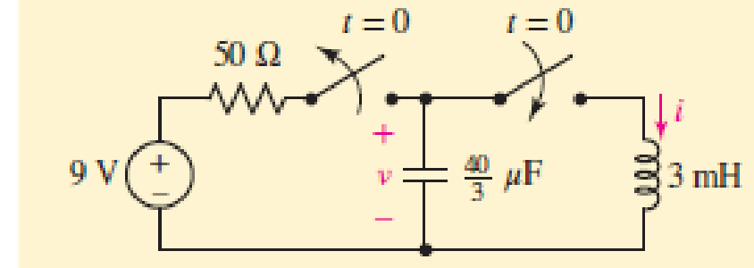
FIGURE 9.36 Circuit for Example 9.11.
Expert Solution & Answer
Want to see the full answer?
Check out a sample textbook solution
Students have asked these similar questions
determine the inductive reactance of rlc series ac circuit given the ff:
rms current=7.5A
voltage=5V
resistance=150ohms
capacitive resitance=160ohm
source average power=2.5W
6. What is the sinusoidal expression of current through circuit contain only capacitor?
(Where C=20μF, v=4 sin(1000t+20) V
What is the product of two complex numbers 4 + 3j and 2+ 2j where j = sqrt (1-) in phasor notation? Write the answer in the form, to make it easy to type, magnitude AT angle in radians.
Chapter 9 Solutions
Loose Leaf for Engineering Circuit Analysis Format: Loose-leaf
Ch. 9.1 - A parallel RLC circuit contains a 100 2 resistor...Ch. 9.2 - After being open for a long time, the switch in...Ch. 9.2 - Prob. 3PCh. 9.2 - Prob. 4PCh. 9.3 - (a) Choose R1 in the circuit of Fig. 9.14 so that...Ch. 9.4 - Prob. 6PCh. 9.5 - Prob. 7PCh. 9.5 - Prob. 8PCh. 9.6 - Let is = 10u(t) 20u(t) A in Fig. 9.31. Find (a)...Ch. 9.6 - Let vs = 10 + 20u(t) V in the circuit of Fig....
Ch. 9.7 - Alter the capacitor value and voltage source in...Ch. 9 - For a certain source-free parallel RLC circuit, R...Ch. 9 - Element values of 10 mF and 2 nH are employed in...Ch. 9 - If a parallel RLC circuit is constructed from...Ch. 9 - Prob. 4ECh. 9 - You go to construct the circuit in Exercise 1,...Ch. 9 - A parallel RLC circuit has inductance 2 mH and...Ch. 9 - Prob. 7ECh. 9 - A parallel RLC circuit has R = 1 k, L = 50 mH. and...Ch. 9 - Prob. 9ECh. 9 - Prob. 10ECh. 9 - The current flowing through a 5 resistor in a...Ch. 9 - For the circuit of Fig.9.40, obtain an expression...Ch. 9 - Consider the circuit depicted in Fig. 9.40. (a)...Ch. 9 - With regard to the circuit represented in Fig....Ch. 9 - (a) Assuming the passive sign convention, obtain...Ch. 9 - With regard to the circuit presented in Fig. 9.42,...Ch. 9 - Obtain expressions for the current i(t) and...Ch. 9 - FIGURE 9.43 Replace the 14 resistor in the...Ch. 9 - Design a complete source-free parallel RLC circuit...Ch. 9 - For the circuit represented by Fig. 9.44, the two...Ch. 9 - Prob. 21ECh. 9 - Prob. 22ECh. 9 - A critically damped parallel RLC circuit is...Ch. 9 - A source-free parallel RLC circuit has an initial...Ch. 9 - A critically damped parallel RLC circuit is...Ch. 9 - For the circuit of Fig. 9.45, is(t) = 30u(t) mA....Ch. 9 - Prob. 27ECh. 9 - The circuit of Fig. 9.44 is rebuilt such that the...Ch. 9 - Prob. 29ECh. 9 - Prob. 30ECh. 9 - The source-free circuit depicted in Fig. 9.1 is...Ch. 9 - (a) Graph the current i for the circuit described...Ch. 9 - Analyze the circuit described in Exercise 31 to...Ch. 9 - A source-free parallel RLC circuit has capacitance...Ch. 9 - Prob. 35ECh. 9 - Obtain an expression for vL(t), t 0, for the...Ch. 9 - For the circuit of Fig. 9.47, determine (a) the...Ch. 9 - (a) Design a parallel RLC circuit that provides a...Ch. 9 - The circuit depicted in Fig. 9.48 is just barely...Ch. 9 - When constructing the circuit of Fig. 9.48, you...Ch. 9 - The circuit of Fig. 9.22a is constructed with a...Ch. 9 - Prob. 42ECh. 9 - Prob. 43ECh. 9 - The simple three-element series RLC circuit of...Ch. 9 - Prob. 45ECh. 9 - Prob. 46ECh. 9 - Prob. 47ECh. 9 - With reference to the series RLC circuit of Fig....Ch. 9 - Obtain an expression for i1 as labeled in Fig....Ch. 9 - The circuit in Fig. 9.52 has the switch in...Ch. 9 - For the circuit in Fig. 9.52, determine the value...Ch. 9 - In the series circuit of Fig. 9.53, set R = 1 ....Ch. 9 - Evaluate the derivative of each current and...Ch. 9 - Consider the circuit depicted in Fig. 9.55. If...Ch. 9 - Prob. 55ECh. 9 - In the circuit shown in Fig. 9.56, (a) obtain an...Ch. 9 - Prob. 57ECh. 9 - For the circuit represented in Fig. 9.57, (a)...Ch. 9 - FIGURE 9.57 Replace the 1 resistor in Fig. 9.57...Ch. 9 - A circuit has an inductive load of 2 H, a...Ch. 9 - (a) Adjust the value of the 3 resistor in the...Ch. 9 - Determine expressions for vC(t) and iL(t) in Fig....Ch. 9 - The capacitor in the LC circuit in Fig. 9.60 has...Ch. 9 - Suppose that the switch in the circuit in Fig....Ch. 9 - The capacitor in the circuit of Fig. 9.63 is set...Ch. 9 - The physical behavior of automotive suspension...Ch. 9 - A lossless LC circuit can be used to provide...
Knowledge Booster


Learn more about
Need a deep-dive on the concept behind this application? Look no further. Learn more about this topic, electrical-engineering and related others by exploring similar questions and additional content below.Similar questions
- 4. Find the phasors corresponding to the followinga. ? ? = 21 cos 4? − 15° ?b. ? ? = −8 sin 10? + 70° ?arrow_forwardWhat impedance vector 10 + j22 represents:A. A pure resistance. C. A pure capacitance.B. A pure inductance. D. An inductance combined with a resistance.arrow_forwardWhat impedance vector (0- j15) Ohms represents:A. A pure resistance. C. A pure capacitance.B. A pure inductance. D. An inductance combined with a capacitance.arrow_forward
- 1. For the following sinusoids, determine which one leads and by how much a. ?(?) = 10cos (4? − 60°) and ?(?) = 6sin (4? + 50°)b. ?ଵ(?) = 4cos (377? + 10°) and ?ଶ(?) = −20cos(377?)c. ?(?) = 13 cos(2?) + 5 sin(2?) and ?(?) = 15cos (2? − 11.8°)arrow_forwardIn the inductor circuit, if the source voltage, V1, is 8.7∠10° Vp, what would be the voltage in RMS?arrow_forwardWrite a Matlab code to sketch using plot function, y(t)=3 sin(t) for 3 periodsarrow_forward
- A circuit has an ac voltage source and a resistor and capacitorconnected in series. There is no inductor. The ac voltage source hasvoltage amplitude 900 V and angular frequency v = 20.0 rad/s. Thevoltage amplitude across the capacitor is 500 V. The resistor has resistanceR = 300 Ω. What is the average rate at which the ac source supplies electrical energy to the circuit?arrow_forwardIn one measurement of the body's bioelectric impedance, values of Z = 4.09 x 10² and = -6.08° are obtained for the total impedance and the phase angle, respectively. These values assume that the body's resistance R is in series with its capacitance C and that there is no inductance L. Determine the body's (a) resistance and (b) capacitive reactance.arrow_forwardA transmission line has a capacitance of 25 pF / ft. and an inductance of 0.15 µh / ft. Determine the characteristic impedance of the line.arrow_forward
- If the phasor voltage across an element is given by V=100∠120∘ and the phasor current through the same element is given by I=50∠30∘, which of the following basic circuit elements best represents this element? a. Insufficient information is given. b. Capacitor c. Some combination of these basic elements d. Resistor e. Inductorarrow_forwardThe following circuit is powered by a polyharmonic voltage whose expression is: v(t) = 100+141.sin (1000t) + 70.7.sin (2000t) V. It is requested: a) The expression of the instantaneous current.b) Plot the amplitude and phase spectra of the voltage and current.c) The values of the apparent, active, reactive and distortion powers, justifying the resultsarrow_forward1. solve equation of the sinusoidal signal v(t) from the information, where v(t) = Vp sin ωt. Vp-p = 6 div Oscilloscope setting: horizontal = 0.5 ms/div 1 cycle = 8 div vertical amplitude = 0.5 volt/div 2. 1 cycle of 2 sinusoidal signals displayed with 10 kHz on the oscilloscope screen. If the two signals have a difference time with 20µs, what the value of phase shift between two signals/waveforms displayed on the scope screen? 3. It is possible for a circuit made up of a resistor, an inductor, and a capacitor (connected in series or parallel) to behave like a purely resistive circuit. Explain why.arrow_forward
arrow_back_ios
SEE MORE QUESTIONS
arrow_forward_ios
Recommended textbooks for you
 Introductory Circuit Analysis (13th Edition)Electrical EngineeringISBN:9780133923605Author:Robert L. BoylestadPublisher:PEARSON
 Delmar's Standard Textbook Of ElectricityElectrical EngineeringISBN:9781337900348Author:Stephen L. HermanPublisher:Cengage Learning
 Programmable Logic ControllersElectrical EngineeringISBN:9780073373843Author:Frank D. PetruzellaPublisher:McGraw-Hill Education
 Fundamentals of Electric CircuitsElectrical EngineeringISBN:9780078028229Author:Charles K Alexander, Matthew SadikuPublisher:McGraw-Hill Education
 Electric Circuits. (11th Edition)Electrical EngineeringISBN:9780134746968Author:James W. Nilsson, Susan RiedelPublisher:PEARSON
 Engineering ElectromagneticsElectrical EngineeringISBN:9780078028151Author:Hayt, William H. (william Hart), Jr, BUCK, John A.Publisher:Mcgraw-hill Education,
Introductory Circuit Analysis (13th Edition)
Electrical Engineering
ISBN:9780133923605
Author:Robert L. Boylestad
Publisher:PEARSON
Delmar's Standard Textbook Of Electricity
Electrical Engineering
ISBN:9781337900348
Author:Stephen L. Herman
Publisher:Cengage Learning
Programmable Logic Controllers
Electrical Engineering
ISBN:9780073373843
Author:Frank D. Petruzella
Publisher:McGraw-Hill Education
Fundamentals of Electric Circuits
Electrical Engineering
ISBN:9780078028229
Author:Charles K Alexander, Matthew Sadiku
Publisher:McGraw-Hill Education
Electric Circuits. (11th Edition)
Electrical Engineering
ISBN:9780134746968
Author:James W. Nilsson, Susan Riedel
Publisher:PEARSON
Engineering Electromagnetics
Electrical Engineering
ISBN:9780078028151
Author:Hayt, William H. (william Hart), Jr, BUCK, John A.
Publisher:Mcgraw-hill Education,
02 - Sinusoidal AC Voltage Sources in Circuits, Part 1; Author: Math and Science;https://www.youtube.com/watch?v=8zMiIHVMfaw;License: Standard Youtube License