
Mechanics of Materials (MindTap Course List)
9th Edition
ISBN: 9781337093347
Author: Barry J. Goodno, James M. Gere
Publisher: Cengage Learning
expand_more
expand_more
format_list_bulleted
Videos
Textbook Question
Chapter 10, Problem 10.6.1P
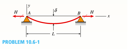
Assume that the deflected shape of a beam AB with immovable pinned supports (see figure) is given by the equation v = -
- For an aluminum-alloy beam with
E = 10 × 106 psi, calculate the tensile stress
Expert Solution & Answer

Trending nowThis is a popular solution!

Chapter 10 Solutions
Mechanics of Materials (MindTap Course List)
Ch. 10 - A propped cantilever steel beam is constructed...Ch. 10 - A fixed-end b earn is subjected to a point load at...Ch. 10 - A propped cantilever beam AB of a length L is...Ch. 10 - A fixed-end beam AB of a length L supports a...Ch. 10 - A cantilever beam AB of a length L has a fixed...Ch. 10 - A cantilever beam of a length L and loaded by a...Ch. 10 - A cantilever beam has a length L and is loaded by...Ch. 10 - A propped cantilever beam of a length L is loaded...Ch. 10 - A propped cantilever beam of a length L is loaded...Ch. 10 - A fixed-end beam of a length L is loaded by a...
Ch. 10 - A fixed-end b earn of a length L is loaded by a...Ch. 10 - A fixed-end beam of a length L is loaded by...Ch. 10 - A counterclockwise moment M0acts at the midpoint...Ch. 10 - A propped cantilever beam of a length L is loaded...Ch. 10 - A propped cantilever beam is subjected to uniform...Ch. 10 - Repeat Problem 10.3-15 using L = 3.5 m, max = 3...Ch. 10 - A two-span, continuous wood girder (E = 1700 ksi)...Ch. 10 - A fixed-end beam AB carries point load P acting at...Ch. 10 - A fixed-end beam AB supports a uniform load of...Ch. 10 - -4-4 A cantilever beam is supported at B by cable...Ch. 10 - A propped cantilever beam AB of a length L carries...Ch. 10 - A beam with a sliding support at B is loaded by a...Ch. 10 - A propped cantilever beam of a length 2L with a...Ch. 10 - The continuous frame ABC has a pin support at /l,...Ch. 10 - The continuous frame ABC has a pin support at A,...Ch. 10 - Beam AB has a pin support at A and a roller...Ch. 10 - The continuous frame ABCD has a pin support at B:...Ch. 10 - Two flat beams AB and CD, lying in horizontal...Ch. 10 - -4-13 A propped cantilever beam of a length 2L is...Ch. 10 - A propped cantilever beam of a length 2L is loaded...Ch. 10 - Determine the fixed-end moments (MAand MB) and...Ch. 10 - A continuous beam ABC wit h two unequal spans, one...Ch. 10 - Beam ABC is fixed at support A and rests (at point...Ch. 10 - A propped cantilever beam has flexural rigidity EI...Ch. 10 - A triangularly distributed 1oad with a maximum...Ch. 10 - A fixed-end beam is loaded by a uniform load q =...Ch. 10 - Uniform load q = 10 lb/ft acts over part of the...Ch. 10 - A propped cantilever beam with a length L = 4 m is...Ch. 10 - A cant i levé r b ea m i s supported by a tie rod...Ch. 10 - The figure shows a nonprismatic, propped...Ch. 10 - A beam ABC is fixed at end A and supported by beam...Ch. 10 - A three-span continuous beam A BCD with three...Ch. 10 - A beam rests on supports at A and B and is loaded...Ch. 10 - A propped cantilever beam is subjected to two...Ch. 10 - A propped cantilever beam is loaded by a...Ch. 10 - A fixed-end beam AB of a length L is subjected to...Ch. 10 - A temporary wood flume serving as a channel for...Ch. 10 - Two identical, simply supported beams AB and CD...Ch. 10 - The cantilever beam AB shown in the figure is an...Ch. 10 - The beam AB shown in the figure is simply...Ch. 10 - The continuous frame ABC has a fixed support at A,...Ch. 10 - The continuous frame ABC has a pinned support at...Ch. 10 - A wide-flange beam ABC rests on three identical...Ch. 10 - A fixed-end beam AB of a length L is subjected to...Ch. 10 - A beam supporting a uniform load of intensity q...Ch. 10 - A thin steel beam AB used in conjunction with an...Ch. 10 - Find an expression for required moment MA(in terms...Ch. 10 - Repeat Problem 10.4-41 for the loading shown in...Ch. 10 - A propped cantilever beam is loaded by two...Ch. 10 - A cable CD of a length H is attached to the third...Ch. 10 - A propped cantilever beam, fixed at the left-hand...Ch. 10 - Solve t he preceding problem by integrating the...Ch. 10 - A two-span beam with spans of lengths L and L/3 is...Ch. 10 - Solve the preceding problem by integrating the...Ch. 10 - Assume that the deflected shape of a beam AB with...Ch. 10 - (a) A simple beam AB with length L and height h...
Knowledge Booster


Learn more about
Need a deep-dive on the concept behind this application? Look no further. Learn more about this topic, mechanical-engineering and related others by exploring similar questions and additional content below.Similar questions
- A uniformly loaded, steel wide-flange beam with simple supports (see figure) has a downward deflection of 10 mm at the midpoint and angles of rotation equal to 0.01 radians at the ends. Calculate the height h of the beam if the maximum bending stress is 90 MPa and the modulus of elasticity is 200 GPa, (Use the formulas of Example 9-L)arrow_forward(a) A simple beam AB with length L and height h supports a uniform load of intensity q (see the figure part a). Obtain a formula for the curvature shortening A of this beam. Also, obtain a formula for the maximum bending stress b in the beam due to the load q. Now assume that the ends of the beam are pinned so that curvature shortening is prevented and a horizontal force H develops at the supports (see the figure part b). Obtain a formula for the corresponding axial tensile stress t . Using the formulas obtained in parts (a) and (b), calculate the curvature shortening , the maximum bending stress b, and the tensile stress t for the following steel beam: length L = 3m, height h = 300 mm, modulus of elasticity E = 200 GPa, and moment of inertia I = 36 x 106 mm4. Also, the load on the beam has intensity q = 25 kN/m. Compare the tensile stress tproduced by the axial forces with the maximum bending stress bproduced by the uniform load.arrow_forward-14 A simply supported composite beam with a 3.6 m span supports a triangularly distributed load of peak intensity q0at mid-span (see figure part a). The beam is constructed of two wood joists, each 50 mm x 280 mm, fastened to two steel plates, one of dimensions 6 mm × 80 mm and the lower plate of dimensions 6 mm x 120mm (see figure part b). The modulus of elasticity for the wood is 11 GPa and for the steel is 210 GPa. If the allowable stresses are 7 MPa for the wood and 120 MPa for the steel, find the allowable peak load intensity q0maxwhen the beam is bent about the z axis. Neglect the weight of the beam.arrow_forward
- A simple beam that is 18 ft long supports a uniform load of intensity q. The beam is constructed of two C8 x 11.5 sections (channel sections or C-shapes) on either side of a 4 × 8 (actual dimensions) wood beam (see the cross section shown in the figure part a). The modulus of elasticity of the steel (E; = 30,000 ksi) is 20 times that of the wood (Ew). (a) If the allowable stresses in the steel and wood are 12,000 psi and 900 psi, respectively, what is the allowable load qmax Note: Disregard the weight of the beam, and see Table F-3(a) of Appendix F for the dimensions and properties of the C-shape beam. (b) If the beam is rotated 90° to bend about its v axis (see figure part b) and uniform load q = 250 lb/ft is applied, find the maximum stresses trs and crw in the steel and wood, respectively Include the weight of the beam. (Assume weight densities of 35 lb/ft3 and 490 lb/ft3 for the wood and steel, respectively.)arrow_forwardA beam with a channel section is subjected to a bending moment M having its vector at an angle 0 to the 2 axis (see figure). Determine the orientation of the neutral axis and calculate the maximum tensile stress et and maximum compressive stress ecin the beam. Use the following data: C 8 × 11.5 section, M = 20 kip-in., tan0=l/3. See Table F-3(a) of Appendix F for the dimensions and properties of the channel section.arrow_forwardA cantilever beam AB with rectangular cross sections of a constant width b and varying height /iT is subjected to a uniform load of intensity q (see figure). How should the height hxvary as a function of .y (measured from the free end of the beam) in order to have a fully stressed beam? (Express hxin terms of the height hBat the fixed end of the beam.)arrow_forward
- A beam with a semicircular cross section of radius r is subjected to a bending moment M having its vector at an angle 9 to the z axis (see figure). Derive formulas for the maximum tensile stress tcand the maximum compressive stress tc in the beam for 0 = 0,45º and 90º, Express the results in the form or A/r where a is a numerical value.arrow_forwardThe cross section of a sand wie h beam consisting of aluminum alloy faces and a foam core is shown in the figure. The width b of the beam is 8.0 in, the thickness I of the faces is 0.25 in., and the height hcof the core is 5.5 in. (total height h = 6.0 in). The moduli of elasticity are 10.5 × 10⁶ psi for the aluminum faces and 12.000 psi for the foam core. A bending moment M = 40 kip-in. acts about the z axis. Determine the maximum stresses in the faces and the core using (a) the general theory for composite beams and (b) the approximate theory for sandwich beams.arrow_forwardThe cantilever beam AB shown in the figure is an S6 × 12.5 steel I-beam with E = 30 × 106 psi. The simple beam DE is a wood beam 4 in. x 12 in. (nominal dimensions) in cross section with E = 1.5 x 10⁶ psi. A steel rod AC of diameter 0.25 in., length 10 ft, and E = 30 x 106 psi serves as a hanger joining the two beams. The hanger fits snugly between the beams before the uniform load is applied to beam DE. Determine the tensile force Fin the hanger and the maximum bending moments MABand MDEin the two beams due to the uniform load, which has an intensity q = 400 lb/ft. Hint: To aid in obtaining the maximum bending moment in beam DE, draw the shear-force and bending-moment diagrams.arrow_forward
- A simple beam ABC having rectangular cross sections with constant height A and varying width bxsupports a concentrated load P acting at the midpoint (see figure). How should the width bxvary as a function of x in order to have a fully stressed beam? (Express bxin terms of the width bgat the midpoint of the beam.)arrow_forwardA cantilever beam with a uniform load (see figure) has a height h equal to 1/8 of the length L. The beam is a steel wide-flange section with E = 28 X 106 psi and an allowable bending stress of 17,500 psi in both tension and compression. Calculate the ratio S/L of the deflection at the free end to the length, assuming that the beam carries the maximum allowable load. (Use the formulas of Example 9-2.)arrow_forwardA cantilever beam AB of length L = 6.5 ft supports a trapezoidal distributed load of peak intensity 4, and minimum intensity q/2tthat includes the weight of the beam (see figure). The beam is a steel W 12 × 14 wide-flange shape (see Table F-l(a), Appendix F). Calculate the maximum permissible load q based upon (a) an allowable bending stress eallow = 18 ksi and (b) an allowable shear stress eallow = 7,5 ksi. Note: Obtain the moment of inertia and section modulus of the beam from Table F-l(a).arrow_forward
arrow_back_ios
SEE MORE QUESTIONS
arrow_forward_ios
Recommended textbooks for you
 Mechanics of Materials (MindTap Course List)Mechanical EngineeringISBN:9781337093347Author:Barry J. Goodno, James M. GerePublisher:Cengage Learning
Mechanics of Materials (MindTap Course List)
Mechanical Engineering
ISBN:9781337093347
Author:Barry J. Goodno, James M. Gere
Publisher:Cengage Learning
Mechanics of Materials Lecture: Beam Design; Author: UWMC Engineering;https://www.youtube.com/watch?v=-wVs5pvQPm4;License: Standard Youtube License