
Concept explainers
Videos
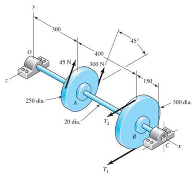
A countershaft carrying two V-belt pulleys is shown in the figure. Pulley A receives power from a motor through a belt with the belt tensions shown. The power is transmitted through the shaft and delivered to the belt on pulley B. Assume the belt tension on the loose side at B is 15 percent of the tension on the tight side.
11-14* to 11-17* For the problem specified in the table, build upon the results of the original problem to obtain a Basic Load Rating for a ball bearing at C with a 95 percent reliability, assuming distribution data from manufacturer 2 in Table 11-6. The shaft rotates at 1200 rev/min, and the desired bearing life is 15 kh. Use an application factor of 1.2.
| Problem Number | Original Problem, Page Number |
| 11-14* | 3-68, 151 |
| 11-15* | 3-69, 151 |
| 11-16* | 3-70, 151 |
| 11-17* | 3-71, 151 |
Want to see the full answer?
Check out a sample textbook solution
Chapter 11 Solutions
Shigley's Mechanical Engineering Design (McGraw-Hill Series in Mechanical Engineering)


- Repeat Problem 11.2-14 using L = 12 ft, ß = 0.25 kips/in., ßRl= 1.5ßL2, and ßR2= 2 ßR1.arrow_forwardRepeat Problem 11.2-3 assuming that R= 10 kN · m/rad and L = 2 m.arrow_forwardA hand cranking lever, as shown in Figure 6 below, is used to start a truck engine byapplying a force F = 400 N. The material of the cranking lever has a yield strength = 320 MPa;Ultimate tensile strength = 500 MPa; Young’s modulus = 205 GPa; Modulus of rigidity = 84 GPaand poisson’s ratio = 0.3. Assuming factor of safety to be 4 based on yield strength, design thediameter of the lever at section X-X near the guide bush using: a) Maximum distortion energytheory; and b) Maximum shear stress theory.arrow_forward
- A Solid steel shaft running at 600rpm is supported on bearings 600mm apart. The shaft receives 40kW through a 400mm diameter pulley weighing 400N located 300mm to the right of left bearing by a vertical flat belt drive. The power is transmitted from the shaft through another pulley of diameter 600mm weighing 600N located 200mm to the right of right bearing. The belt drives are at right angles to each other and ratio of belt tensions is 3. Determine the size of the shaft necessary, if the allowable shear stress in the shaft material is 40MPa and the loads are steady.arrow_forwardA belt conveyor transports 18 tonnes per hr at 20°. Determine the speed reducer power factor to lift the load vertically up sufficient to give 33.5 m horizontal center-to-center pulley distance. 1750-rpm motor, plain chain drive to helical gear speed reducer. Belt speed, 61 m/min. Discharge over tail pulley. No tripper.arrow_forwardA link has a load factor of 0.80 the surface factor of 0.80. The surface factor is 0.92 and the endurance strength is 28000 psi. Compute the alternating stress of the link if it is subjected to a reversing load. Assume a factor of safety of 3. A. 8150 B. 10920 C. 9,333 D. 7260 Please solve the Problem elaborately and Refer Machine Elements and Stresses Equations from the figures or use other shortcut Methods you have or you may Solve both or in more different methods the better ?. Your solution will be use as reference for my Future Board Exam preparation/review/study. Thank you so much dear your work will be appreciated much and rated excellently.arrow_forward
- The figure 1 shows a pulley assembly that consists of a shaft supported by two bearings and driven by a motor on the righthand side (not shown in the figure). The shaft diameter is 100mm. The pulley consists of two disks, each disk is 15 mm thick and has an outer diameter of 620mm, that are connected by means of a cylindrical shell. The length of the shell is 500mm, the outer diameter of the shell is 600mm, and the thickness of the shell is 15mm. The pulley drives a belt that places a uniformly distributed load on the shell (of 100000N) as shown in the diagram. The belt lifts a load that applies a torque of 6000Nm to the pulley. The shell and the plates are connected. A 6mm fillet should be applied to all the 90 degree corners between the shaft and the plates and between the shell and the plates. The deflection of the shaftarrow_forwardThe figure 1 shows a pulley assembly that consists of a shaft supported by two bearings and driven by a motor on the righthand side (not shown in the figure). The shaft diameter is 100mm. The pulley consists of two disks, each disk is 15 mm thick and has an outer diameter of 620mm, that are connected by means of a cylindrical shell. The length of the shell is 500mm, the outer diameter of the shell is 600mm, and the thickness of the shell is 15mm. The pulley drives a belt that places a uniformly distributed load on the shell (of 100000N) as shown in the diagram. The belt lifts a load that applies a torque of 6000Nm to the pulley. The shell and the plates are connected. A 6mm fillet should be applied to all the 90 degree corners between the shaft and the plates and between the shell and the plates. The highest stress in the systemarrow_forwardThe figure 1 shows a pulley assembly that consists of a shaft supported by two bearings and driven by a motor on the righthand side (not shown in the figure). The shaft diameter is 100mm. The pulley consists of two disks, each disk is 15 mm thick and has an outer diameter of 620mm, that are connected by means of a cylindrical shell. The length of the shell is 500mm, the outer diameter of the shell is 600mm, and the thickness of the shell is 15mm. The pulley drives a belt that places a uniformly distributed load on the shell (of 100000N) as shown in the diagram. The belt lifts a load that applies a torque of 6000Nm to the pulley. The shell and the plates are connected. A 6mm fillet should be applied to all the 90 degree corners between the shaft and the plates and between the shell and the plates. Apply the boundary conditions and the forces and torques to the system and determine the following: Calculate the highest Principal stresses in the system ?arrow_forward
- The worm shaft shown in the figure transmits 1-kW at 500 rev/min. A static forceanalysis results are also shown in the figure. Bearing A is to be an angular-contact ballbearing mounted to take the 2.75 kN thrust load. The bearing at B is to take only theradial load, so a straight roller bearing will be employed. Use an application factor of1.2, a desired life of 25 kh, and a combined reliability goal of 0.99. (a)Specify each bearing by giving all required charecteristics. (b) Determine the radial and thrust components of loads on each bearing. (c) Make a design assessment for each bearing and of the system.arrow_forwardA plate clutch has 3 discs on the driving shaft and 2 discs on the driven shaft, providing four pairs of contact surfaces. The outside diameter of the contact surfaces is 240 mm and inside diameter 120 mm. Assuming uniform pressure and coeff. Of friction is 0.3. Find the total spring load pressing the plates together to transmit 23kw power at 1475 revolution per minute. If there 6 springs each of stiffness 13 kN/m and each of the contact surfaces has worn away by 1.25 mm. find the maximum power that can be transmitted assuming uniform wear. A plate clutch has 3 discs on the driving shaft and 2 discs on the driven shaft, providing four pairs of contact surfaces. The outside diameter of the contact surfaces is 240 mm and inside diameter 120 mm. Assuming uniform pressure and coeff. Of friction is 0.3. Find the total spring load pressing the plates together to transmit 23kw power at 1475 revolution per minute. If there 6 springs each of stiffness 13 kN/m and each of the contact surfaces…arrow_forwardIn the design in the figure, a force of Fn=45992 N acts in the vertical plane on a machine element with a diameter of D=200 mm on the shaft resting on the A and B bearings. If the angle made by this force with the horizontal is b=40o, find the life of the 6210 coded Deep Ball bearing to be used in the B bearing, in hours. Number of revolutions = 30 rpm. 1-) The diameter of the machine element on which the force acts will be taken into account in the calculation of bearing forces (That is, it will be assumed that the Fn force AFFECTS THE GROUND shown in the figure, NOT the axis of the shaft). 2-) Pi number will be taken as 3.14.arrow_forward
 Mechanics of Materials (MindTap Course List)Mechanical EngineeringISBN:9781337093347Author:Barry J. Goodno, James M. GerePublisher:Cengage Learning