
Shigley's Mechanical Engineering Design (McGraw-Hill Series in Mechanical Engineering)
10th Edition
ISBN: 9780073398204
Author: Richard G Budynas, Keith J Nisbett
Publisher: McGraw-Hill Education
expand_more
expand_more
format_list_bulleted
Videos
Textbook Question
Chapter 11, Problem 28P
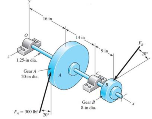
Repeat the requirements of Prob. 11-27 for the bearing at the left end of the shaft.
The shaft shown in the figure is proposed as a preliminary design for the application defined in Prob. 3-72, p. 152. The effective centers of the gears for force transmission are shown. The dimensions for the bearing surfaces (indicated with cross markings) have been estimated. The shaft rotates at 1200 rev/min, and the desired bearing life is 15 kh with a 95 percent reliability in each bearing, assuming distribution data from manufacturer 2 in Table 11-6. Use an application factor of 1.2.
Obtain a Basic Load Rating for a ball bearing at the right end.
Expert Solution & Answer
Want to see the full answer?
Check out a sample textbook solution
Students have asked these similar questions
A straight gear with module m = 5 mm and face width bw = 40 mm has center distance cd = 0.1875m. The pinion has 25 teeth, the speed is 1000 rpm, and pressure angle ᶲ = 200. Find the Hertzian contact stress at the pitch point when the gear transmits 10 kW. Neglect friction forces. The gear steel has modulus of elasticity E = 207 GPa and a Poisson’s ratio of 0.30.
A 15 kW and 1200 r.p.m. motor drives a compressor at 300
r.p.m. through a pair of spur gears having
20° stub teeth. The centre to centre distance between the shafts
is 400 mm. The motor pinion is made
of forged steel having an allowable static stress as 210 MPa,
while the gear is made of cast steel
having allowable static stress as 140 MPa. Assuming that the
drive operates 8 to 10 hours per day
under light shock conditions, find from the standpoint of
strength,
1. Module; 2. Face width and 3. Number of teeth and pitch circle
diameter of each gear.
Check the gears thus designed from the consideration of wear.
The surface endurance limit may be
taken as 700 MPa
A 15 kW and 1200 r.p.m. motor drives a compressor at 300 r.p.m. through a pair of spur gears having 20° stub teeth. The centre to centre distance between the shafts is 400 mm. The motor pinion is made of forged steel having an allowable static stress as 210 MPa, while the gear is made of cast steel having allowable static stress as 140 MPa. Assuming that the drive operates 8 to 10 hours per day under light shock conditions, find from the standpoint of strength, 1. Module; 2. Face width and 3. Number of teeth and pitch circle diameter of each gear. Check the gears thus designed from the consideration of wear. The surface endurance limit may be taken as 700 MP
Chapter 11 Solutions
Shigley's Mechanical Engineering Design (McGraw-Hill Series in Mechanical Engineering)
Ch. 11 - Manufacturer Rating Life, Revolutions Weibull...Ch. 11 - Manufacturer Rating Life, Revolutions Weibull...Ch. 11 - Manufacturer Rating Life, Revolutions Weibull...Ch. 11 - Problems 112 and 113 raise the question of the...Ch. 11 - Prob. 5PCh. 11 - Manufacturer Rating Life, Revolutions Weibull...Ch. 11 - Two ball bearings from different manufacturers are...Ch. 11 - 11-8 to 11-13 For the bearing application...Ch. 11 - 11-8 to 11-13 For the bearing application...Ch. 11 - 11-8 to 11-13 For the bearing application...
Ch. 11 - 11-8 to 11-13 For the bearing application...Ch. 11 - 11-8 to 11-13 For the bearing application...Ch. 11 - 11-8 to 11-13 For the bearing application...Ch. 11 - A countershaft carrying two V-belt pulleys is...Ch. 11 - A countershaft carrying two V-belt pulleys is...Ch. 11 - A countershaft carrying two V-belt pulleys is...Ch. 11 - A countershaft carrying two V-belt pulleys is...Ch. 11 - For the shaft application defined in Prob. 3-77,...Ch. 11 - For the shaft application defined in Prob. 3-79,...Ch. 11 - An 02-series single-row deep-groove ball bearing...Ch. 11 - An 02-series single-row deep-groove ball bearing...Ch. 11 - 11-22 to 11-26 An 02-series single-row deep-groove...Ch. 11 - 1122 to 1126 An 02-series single-row deep-groove...Ch. 11 - 1122 to 1126 An 02-series single-row deep-groove...Ch. 11 - 1122 to 1126 An 02-series single-row deep-groove...Ch. 11 - 1122 to 1126 An 02-series single-row deep-groove...Ch. 11 - The shaft shown in the figure is proposed as a...Ch. 11 - Repeat the requirements of Prob. 11-27 for the...Ch. 11 - The shaft shown in the figure is proposed as a...Ch. 11 - Repeat the requirements of Prob. 11-29 for the...Ch. 11 - Shown in the figure is a gear-driven squeeze roll...Ch. 11 - The figure shown is a geared countershaft with an...Ch. 11 - The figure is a schematic drawing of a...Ch. 11 - A gear-reduction unit uses the countershaft...Ch. 11 - The worm shaft shown in part a of the figure...Ch. 11 - In bearings tested at 2000 rev/min with a steady...Ch. 11 - A 16-tooth pinion drives the double-reduction...Ch. 11 - Estimate the remaining life in revolutions of an...Ch. 11 - The same 02-30 angular-contact ball bearing as in...Ch. 11 - A countershaft is supported by two tapered roller...Ch. 11 - For the shaft application defined in Prob. 3-74,...Ch. 11 - For the shaft application defined in Prob. 3-76,...Ch. 11 - Prob. 43PCh. 11 - The gear-reduction unit shown has a gear that is...
Knowledge Booster


Learn more about
Need a deep-dive on the concept behind this application? Look no further. Learn more about this topic, mechanical-engineering and related others by exploring similar questions and additional content below.Similar questions
- A steel shaft 800 mm long transmitting 15 kW at 400 r.p.m. is supported at two bearings at the twoends. A gear wheel having 80 teeth and 500 mm pitch circle diameter is mounted at 200 mm from theleft hand side bearing and receives power from a pinion meshing with it. The axis of pinion and gearlie in the horizontal plane. A pulley of 300 mm diameter is mounted at 200 mm from right hand sidebearing and is used for transmitting power by a belt. The belt drive is inclined at 30° to the vertical inthe forward direction. The belt lap angle is 180 degrees. The coefficient of friction between belt andpulley is 0.3. Design and sketch the arrangement of the shaft assuming the values of safe stresses as :τ = 55 MPa; σt= 80 MPa. Take torsion and bending factor 1.5 and 2 respectively.arrow_forwardA Coniflex, straight-tooth bevel gearset is supported on shafts with centerlines intersecting at a 90° angle. The gear is straddle mounted between closely positioned bearings, and the pinion overhangs its support bearing. The 15-tooth pinion rotates at 900 rpm, driving the 60-tooth gear, which has a di- ametral pitch of 6, pressure angle of 20°, and face width of 1.25 inches. The material for both gears is through-hardened Grade I steel with a hardness of BHN 300 (see Figure). It is desired to have a reliability of 90 percent, a design life of 10° cy- cles, and a governing safety factor of 2.5. Estimate the maximum horsepower that can be transmitted by this gear re- ducer while meeting all of the design specifications given.arrow_forwardA helical cast steel gear with 30o helix angle has to transmit 35 kW at 2000 rpm. If the gears has 25 teeth, find the necessary module, pitch diameters and face width for 20o full depth involute teeth. The static stress for cast steel may be taken as 100 MPa. The face width may be taken as 3 times to normal pitch. The tooth form factor is given by the expression y'= 0.154-0.912/TE, where TE represents the equivalent number of teeth. the velocity factor is given by Cv=6/(6+v), where v is the peripheral speed of the gear in m/s.arrow_forward
- A pair of 20º full depth involute teeth bevel gears connect two shafts at right angles having velocity ratio 3 : 1. The gear is made of cast iron having allowable static stress as 70 MPa and the 20teeth pinion is of steel with allowable static stress as 100 MPa and 200BHN. The pinion works at 750 r.p.m. Determine the maximum power can be transmitted by the gears if the module is 10mm. Kf=1.4arrow_forward13-32 The 247 6-pitch 20° pinion 2 shown in the figure rotates clockwise at 1000 rev/min and is driven at a power of 25 hp. Gears 4, 5, and 6 have 24, 36, and 144 teeth, respectively. What torque can arm 3 deliver to its output shaft? Draw free-body diagrams of the arm and of each gear and show all forces that act upon them.arrow_forwardAn engine of a motor vehicle with a wheel diameter of 712 mm develops 50 kW at 2,000 rpm combined efficiencyof the differential and transmission is 75% with an over-all speed reduction to. 1 determine he torque to bedelivered by the clutch N-m.arrow_forward
- A 15KW and 1200r.p.m motor drives a compressor at 300r.p.m through a pair of spur gears having 20° stub teeth .the centre to centre distance between the shafts is 400mm.the motor pinion is made to forged steel having an allowable static stress 210MPa while the gear is made of cast steel having an allowable static stress as 140MPa.Assuming that the drive operates 8 to 10 hours per day under light shock conditions,find from the standpoint of strength (a) Module;(b)face width and (c)number of teeth an pitch circle diameter of each gear.check the gears thus designed from the consideration of wear .the surface endurance limit may be taken as 700MPa.arrow_forwardA 15 kW and 1200 motor drives a compressor at 300 a pair of spur gears having . The center-to-center distance between the shafts is 400 . The motor pinion is made of forged steel having an allowable static stress as 210 MPa, while the gear is made of cast steel having allowable static stress as 140 MPa . Assuming that the drive operates 8 to 10 hours per day under light conditions , find from the standpoint of strength Module , 2. Fare and 3. Number of teeth and pitch circle diameter of each gear 2. Check the gears thus designed from the consideration of Static tooth load or endurance strength of the tooth flexural endurance limil (sigma_{\epsilon}) may be taken as 400 MPa 3. Check the gears thus designed from the consideration of wear surface endurance limit ( sigma epsilon x ) may be taken 700 MPa b ^ pi ( 6.154 - 0512/pi; F_{N}arrow_forwardThe reducer input shaft shown in the figure is taperedIt transmits moment with the help of a gear wheel.On the spindle, Fa = 552 N, Fr = 457 N, Ft = 1960 Nfrom gear forces and belt mechanismincoming Fk = 2600 N radial force impact. The shaft rotates with n = 1090 rpm.Accept the shaft diameter in the A bearing as dA = 35 mm.Fixed ball bearing for Lh = 13500 hselectarrow_forward
- A compound shaft drives three gears, as shown. Segments (1) and (2) of the compound shaft are hollow bronze [G = 6,500 ksi] tubes, which have an outside diameter of 2.40 in. and a wall thickness of 0.1375 in. Segments (3) and (4) are solid 1.00-in.-diameter steel [G = 11,500 ksi] shafts. The shaft lengths are L1 = 58 in., L2 = 16 in., L3 = 16 in., and L4 = 28 in. The torques applied to the shafts have magnitudes of TB = 970 lb·ft, TD = 430 lb·ft, and TE = 170 lb·ft, acting in the directions shown. The bearings shown allow the shaft to turn freely. Using the sign convention presented in Section 6.6., calculate: (a) the magnitude of the maximum shear stress in the compound shaft. (b) the rotation angle of flange C with respect to flange A. (c) the rotation angle of gear E with respect to flange A.arrow_forwardAs seen in the figure, a construction machine is rotated by a drive mechanism consisting of belt-pulley and spur gear mechanisms. Engine power P = 5.5 kW ; engine shaft speednm = 1500 rpm ; drive pulley diameter Dt = 16 cm ; diameter of the opposite pulley Dk = 55 cm ; number of pinion teeth z1 = 21 ; number of teeth of the counter gearz2 = 60 ; pulley mechanism efficiency ηk = 0.95 ; Since the efficiency of the gear mechanism is ηd = 0.97: a) Find the output shaft speed nç and the torque Mç on this shaft.b) The force on the taut arm of the belt S1 = 450 N;coefficient of friction μ = 0.3 ; If the winding angle α = 160⁰, is the frictionally transmitted moment Ms sufficient to compensate for the Mg moment on the input shaft? Calculate.arrow_forwardA short stub shaft, made of SAE 1035, as rolled, receivers 30 hp at 300 rpm via a 12-in. spur gear, the power being delivered to another shaft through a flexible coupling. The gear is keyed (profile keyway) midway between the bearings. The pressure angle of the gear teeth 20o, N = 1.5 based on the octahedral shear stress theory with varying stresses. (a) Neglecting the radial component R of the tooth load W , determine the shaft diameter. (b) Considering both the tangential and the radial components, compute the shaft diameters. (c) Is the difference in the results of the parts (a) and (b) enough to change your choice of the shaft size?arrow_forward
arrow_back_ios
SEE MORE QUESTIONS
arrow_forward_ios
Recommended textbooks for you
 Elements Of ElectromagneticsMechanical EngineeringISBN:9780190698614Author:Sadiku, Matthew N. O.Publisher:Oxford University Press
 Mechanics of Materials (10th Edition)Mechanical EngineeringISBN:9780134319650Author:Russell C. HibbelerPublisher:PEARSON
 Thermodynamics: An Engineering ApproachMechanical EngineeringISBN:9781259822674Author:Yunus A. Cengel Dr., Michael A. BolesPublisher:McGraw-Hill Education
 Control Systems EngineeringMechanical EngineeringISBN:9781118170519Author:Norman S. NisePublisher:WILEY
 Mechanics of Materials (MindTap Course List)Mechanical EngineeringISBN:9781337093347Author:Barry J. Goodno, James M. GerePublisher:Cengage Learning
 Engineering Mechanics: StaticsMechanical EngineeringISBN:9781118807330Author:James L. Meriam, L. G. Kraige, J. N. BoltonPublisher:WILEY
Elements Of Electromagnetics
Mechanical Engineering
ISBN:9780190698614
Author:Sadiku, Matthew N. O.
Publisher:Oxford University Press
Mechanics of Materials (10th Edition)
Mechanical Engineering
ISBN:9780134319650
Author:Russell C. Hibbeler
Publisher:PEARSON
Thermodynamics: An Engineering Approach
Mechanical Engineering
ISBN:9781259822674
Author:Yunus A. Cengel Dr., Michael A. Boles
Publisher:McGraw-Hill Education
Control Systems Engineering
Mechanical Engineering
ISBN:9781118170519
Author:Norman S. Nise
Publisher:WILEY
Mechanics of Materials (MindTap Course List)
Mechanical Engineering
ISBN:9781337093347
Author:Barry J. Goodno, James M. Gere
Publisher:Cengage Learning
Engineering Mechanics: Statics
Mechanical Engineering
ISBN:9781118807330
Author:James L. Meriam, L. G. Kraige, J. N. Bolton
Publisher:WILEY
BEARINGS BASICS and Bearing Life for Mechanical Design in 10 Minutes!; Author: Less Boring Lectures;https://www.youtube.com/watch?v=aU4CVZo3wgk;License: Standard Youtube License