
Videos
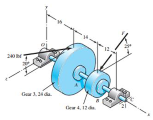
A gear-reduction unit uses the countershaft depicted in the figure. Find the two bearing reactions. The beatings are to be angular-contact ball bearings, having a desired life of 50 kh when used at 300 rev/min. Use 1.2 for the application factor and a reliability goal for the bearing pair of 0.96, assuming distribution data from manufacturer 2 in Table 11-6. Select the bearings from Table 11-2.
Problem 11-34
Dimensions in inches.
The reaction load at point O
The reaction load at point C
The bore diameter of angular contact ball bearing at point O.
The bore diameter of angular contact ball bearing at point C.
Answer to Problem 34P
The reaction load at point O is
The reaction load at point C is
The bore diameter of angular contact ball bearing at point O is 17 mm.
The bore diameter of angular contact ball bearing at point C is 35 mm.
Explanation of Solution
Write the expression for net force in y direction at point A.
Here, net force in y direction at point A is
Write the expression for net force in z direction at point A.
Write the expression for net force in y direction at point B.
Here, net force in y direction at point B is
Write the expression for net force in z direction at point B.
Here, net force in y direction at point B is
Write the expression for net torque on shaft.
Here, radius of gear at point A is
Write the expression for moment equilibrium in
Here, the moment is
Write the expression for moment equilibrium in
Here, the reaction force at C in z direction is
Write the expression for static force equilibrium in
Here, the force is
Write the expression for static force equilibrium in
Here, the force is
Write the expression for resultant force at point O.
Here, the resultant force at point O is
Write the expression for resultant force at point C.
Here, the resultant force at point C is
Write the expression for desired reliability.
Here, the desired reliability is
Write the expression for multiple of dating life.
Here, the multiple of rating life is
Write the expression for catalogue load rating at point O.
Here the catalogue load rating is
Write the expression for catalogue load rating at point C.
Here the catalogue load rating is
Conclusion:
Substitute
Substitute
Substitute
Substitute
Substitute
Substitute
Substitute
Substitute
Substitute
Substitute
Substitute
Substitute
Thus the reaction load at point O is
Substitute
Thus the reaction load at point C is
Substitute 0.96 for
Substitute
Refer to Table 11-6 “Typical Weibull Parameters for Two Manufacturers” to obtain values of
Substitute
Refer to Table 11-2 “Dimensions and Load Ratings for Single-Row 02-Series Deep-Groove and Angular-Contact Ball Bearing” to obtain 17 mm bore size angular contact ball bearing corresponding to
Thus the Bore diameter of angular contact ball bearing at point O is 17 mm.
Substitute
Refer to Table 11-2 “Dimensions and Load Ratings for Single-Row 02-Series Deep-Groove and Angular-Contact Ball Bearing” to obtain 35 mm bore size angular contact ball bearing corresponding to
Thus Bore diameter of angular contact ball bearing at point C is 35 mm.
Want to see more full solutions like this?
Chapter 11 Solutions
Shigley's Mechanical Engineering Design (McGraw-Hill Series in Mechanical Engineering)


- .........A shaft rotating at 150 rpm is subjected to variable load: 8 kN during 60% of the time and 2 kN during 40% of the time. Calculate the basic dynamic load rating in kN for the roller bearing (k = 10/3) for 7200 hours of operation with not more than 10% failures.arrow_forwardThe module and the number of teeth on the pinion of a spur gear are 12mm and 15teeth respectively.A power of 400kW is to be transmitted at 1700rpm of width.if the involute teeth are of standard proportions (addendum=m) with the pressure angle of 22.5° determine (A) torque due to power delivered (B) tangential load (C) teeth width (E)load on the bearingsarrow_forwardb) Design a single row deep groove ball bearing with basic dynamic load rating of 33 KN to be used in a turbine to carry a radial load of 1584 N. The expected life of the bearing is 5591 hours at 529 rpm. Take k=3 for all types of ball bearings. Take the value of the shock load factor as 1.8. The radial and axial load factors are 1.3 and 1.6 respectively and the rotational factor is 1. Calculate: i) Expected life of bearings in millions of revolutions ii) Design equivalent dynamic load in N iii) Basic equivalent dynamic load in N iv) Axial load acting on the bearing in Narrow_forward
- A belt conveyor transports 18 tonnes per hr at 20°. Determine the speed reducer power factor to lift the load vertically up sufficient to give 33.5 m horizontal center-to-center pulley distance. 1750-rpm motor, plain chain drive to helical gear speed reducer. Belt speed, 61 m/min. Discharge over tail pulley. No tripper.arrow_forwardi) Explain the static rating of rolling contact bearings. ii) Write any three technical reasons why ball and roller bearings need to be lubricated. b) Design a self-aligning ball bearing to be used in a turbine to carry a combined radial load of 4466 N and thrust load of 1420 N. The basic dynamic load rating of the bearing is 31 kN at 547 rpm. Take k=3 for all types of ball bearings. Take the value of the shock load factor as 1.3. The axial and radial load factors are 1.8 and 1.2 respectively and the rotational factor is 1. Calculate: i) Basic equivalent dynamic load in N ii) Design equivalent dynamic load in N iii) Expected life of bearings in hoursarrow_forwardA certain application requires a ball bearing with the inner ring rotating, with a design life of 26 kh at a speed of 455 rev/min. The radial load is 2.5 kN and an application factor of 1.2 is appropriate. The reliability goal is 0.92. Find the multiple of rating life required, xD , and the catalog rating C10 with which to enter a bearing table. Choose a 02-series deep-groove ball bearing from Table 11–2 and estimate the reliability in use.arrow_forward
- A truck equipped with a 50 HP engine uses a roller chain as the final drive to the rear axle. The driving sprocket runs at 225 rpm with a center distance of approximately 500 fpm. The transmission efficiency between the engine and the driving sprocket is 85%. 1.1 Determine the pitch and width of chain to be used. 1.2 Determine the number of teeth in each sprocket and the pitch diameters.arrow_forwardThe shaft of a belt drive is made of AISI C1020 as rolled steel. The belt tensions vary continuously during transmission at a constant tension ratio of 3:1; the maximum tight side tension being 400 lb and the minimum tight side tension is expected to be 160 lb, at a pulley diameter of 12 inches. For a Goodman factor of safety of 1.8, recommend the diameter of the shaft. Consider a machined surface and the effect of a hardened profile keyway in the shaft.arrow_forwardb) Design a self-aligning ball bearing with basic dynamic load rating of 69.5 KN to be used in the automobile industry to carry a thrust load of 1184 N. The expected life of the bearing is 5201 hours at 628 rpm. Take k=3 for all types of ball bearings. Take the value of the shock load factor as 1.7 and radial and axial load factors are 1.4 and 2.2 respectively, the rotational factor is 1. Calculate: i) Expected life of bearings in millions of revolutions ii) Design equivalent dynamic load in N iii) Basic equivalent dynamic load in N iv) Radial load acting on the bearing in Narrow_forward
- A single deep grove ball bearing series 3, the outer ring rotates at 1500 rpm with little shock load. Bearing has a bore diameter of 45 mm, working with a load 1890 lb radial and 1250 lb axial load. Determine the rated life and median life of the bearing. Use the design factors according to the attached table.arrow_forwardConsider the belt drive having a diameter of 150 mm that is mounted on the overhung end of ashaft, 30 mm from the nearest bearing. The stepped shaft is made of steel having Su = 965 MPa(140 ksi). The shaft diameter, d, is 30 mm. The bearing bore, D, is 36 mm. The fillet with amachined surface has a radius, r, of 3 mm. What is the safety factor with respect to eventualfatigue failure of the shaft?arrow_forwardA chain drive using bush roller chain transmits 5.6 kW of power. The driving shaft on an electric motor runs at 1440 r.p.m. and velocity ratio is 5. The centre distance of the drive is restricted to 550 ± 2% mm and allowable pressure on the pivot joint is not to exceed 10 N/mm2. The drive is required to operate continuously with periodic lubrication and driven machine is such that load can be regarded as fairly constant with jerk and impact. Design the chain drive by calculating leading dimensions, number of teeth on the sprocket and specify the breaking strength of the chain. Assume a factor ofarrow_forward
 Elements Of ElectromagneticsMechanical EngineeringISBN:9780190698614Author:Sadiku, Matthew N. O.Publisher:Oxford University Press
 Mechanics of Materials (10th Edition)Mechanical EngineeringISBN:9780134319650Author:Russell C. HibbelerPublisher:PEARSON
 Thermodynamics: An Engineering ApproachMechanical EngineeringISBN:9781259822674Author:Yunus A. Cengel Dr., Michael A. BolesPublisher:McGraw-Hill Education
 Control Systems EngineeringMechanical EngineeringISBN:9781118170519Author:Norman S. NisePublisher:WILEY
 Mechanics of Materials (MindTap Course List)Mechanical EngineeringISBN:9781337093347Author:Barry J. Goodno, James M. GerePublisher:Cengage Learning
 Engineering Mechanics: StaticsMechanical EngineeringISBN:9781118807330Author:James L. Meriam, L. G. Kraige, J. N. BoltonPublisher:WILEY