
Shigley's Mechanical Engineering Design (McGraw-Hill Series in Mechanical Engineering)
10th Edition
ISBN: 9780073398204
Author: Richard G Budynas, Keith J Nisbett
Publisher: McGraw-Hill Education
expand_more
expand_more
format_list_bulleted
Concept explainers
Videos
Textbook Question
Chapter 11, Problem 27P
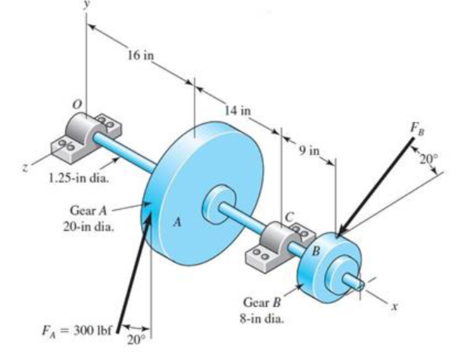
The shaft shown in the figure is proposed as a preliminary design for the application defined in Prob. 3-72, p. 152. The effective centers of the gears for force transmission are shown. The dimensions for the bearing surfaces (indicated with cross markings) have been estimated. The shaft rotates at 1200 rev/min, and the desired bearing life is 15 kh with a 95 percent reliability in each bearing, assuming distribution data from manufacturer 2 in Table 11-6. Use an application factor of 1.2.
Obtain a Basic Load Rating for a ball bearing at the right end.
Expert Solution & Answer
Want to see the full answer?
Check out a sample textbook solution
Students have asked these similar questions
A straight gear with module m = 5 mm and face width bw = 40 mm has center distance cd = 0.1875m. The pinion has 25 teeth, the speed is 1000 rpm, and pressure angle ᶲ = 200. Find the Hertzian contact stress at the pitch point when the gear transmits 10 kW. Neglect friction forces. The gear steel has modulus of elasticity E = 207 GPa and a Poisson’s ratio of 0.30.
A 15 kW and 1200 r.p.m. motor drives a compressor at 300
r.p.m. through a pair of spur gears having
20° stub teeth. The centre to centre distance between the shafts
is 400 mm. The motor pinion is made
of forged steel having an allowable static stress as 210 MPa,
while the gear is made of cast steel
having allowable static stress as 140 MPa. Assuming that the
drive operates 8 to 10 hours per day
under light shock conditions, find from the standpoint of
strength,
1. Module; 2. Face width and 3. Number of teeth and pitch circle
diameter of each gear.
Check the gears thus designed from the consideration of wear.
The surface endurance limit may be
taken as 700 MPa
A 15 kW and 1200 r.p.m. motor drives a compressor at 300 r.p.m. through a pair of spur gears having 20° stub teeth. The centre to centre distance between the shafts is 400 mm. The motor pinion is made of forged steel having an allowable static stress as 210 MPa, while the gear is made of cast steel having allowable static stress as 140 MPa. Assuming that the drive operates 8 to 10 hours per day under light shock conditions, find from the standpoint of strength, 1. Module; 2. Face width and 3. Number of teeth and pitch circle diameter of each gear. Check the gears thus designed from the consideration of wear. The surface endurance limit may be taken as 700 MP
Chapter 11 Solutions
Shigley's Mechanical Engineering Design (McGraw-Hill Series in Mechanical Engineering)
Ch. 11 - Manufacturer Rating Life, Revolutions Weibull...Ch. 11 - Manufacturer Rating Life, Revolutions Weibull...Ch. 11 - Manufacturer Rating Life, Revolutions Weibull...Ch. 11 - Problems 112 and 113 raise the question of the...Ch. 11 - Prob. 5PCh. 11 - Manufacturer Rating Life, Revolutions Weibull...Ch. 11 - Two ball bearings from different manufacturers are...Ch. 11 - 11-8 to 11-13 For the bearing application...Ch. 11 - 11-8 to 11-13 For the bearing application...Ch. 11 - 11-8 to 11-13 For the bearing application...
Ch. 11 - 11-8 to 11-13 For the bearing application...Ch. 11 - 11-8 to 11-13 For the bearing application...Ch. 11 - 11-8 to 11-13 For the bearing application...Ch. 11 - A countershaft carrying two V-belt pulleys is...Ch. 11 - A countershaft carrying two V-belt pulleys is...Ch. 11 - A countershaft carrying two V-belt pulleys is...Ch. 11 - A countershaft carrying two V-belt pulleys is...Ch. 11 - For the shaft application defined in Prob. 3-77,...Ch. 11 - For the shaft application defined in Prob. 3-79,...Ch. 11 - An 02-series single-row deep-groove ball bearing...Ch. 11 - An 02-series single-row deep-groove ball bearing...Ch. 11 - 11-22 to 11-26 An 02-series single-row deep-groove...Ch. 11 - 1122 to 1126 An 02-series single-row deep-groove...Ch. 11 - 1122 to 1126 An 02-series single-row deep-groove...Ch. 11 - 1122 to 1126 An 02-series single-row deep-groove...Ch. 11 - 1122 to 1126 An 02-series single-row deep-groove...Ch. 11 - The shaft shown in the figure is proposed as a...Ch. 11 - Repeat the requirements of Prob. 11-27 for the...Ch. 11 - The shaft shown in the figure is proposed as a...Ch. 11 - Repeat the requirements of Prob. 11-29 for the...Ch. 11 - Shown in the figure is a gear-driven squeeze roll...Ch. 11 - The figure shown is a geared countershaft with an...Ch. 11 - The figure is a schematic drawing of a...Ch. 11 - A gear-reduction unit uses the countershaft...Ch. 11 - The worm shaft shown in part a of the figure...Ch. 11 - In bearings tested at 2000 rev/min with a steady...Ch. 11 - A 16-tooth pinion drives the double-reduction...Ch. 11 - Estimate the remaining life in revolutions of an...Ch. 11 - The same 02-30 angular-contact ball bearing as in...Ch. 11 - A countershaft is supported by two tapered roller...Ch. 11 - For the shaft application defined in Prob. 3-74,...Ch. 11 - For the shaft application defined in Prob. 3-76,...Ch. 11 - Prob. 43PCh. 11 - The gear-reduction unit shown has a gear that is...
Knowledge Booster


Learn more about
Need a deep-dive on the concept behind this application? Look no further. Learn more about this topic, mechanical-engineering and related others by exploring similar questions and additional content below.Similar questions
- A short stub shaft, made of SAE 1035, as rolled, receivers 30 hp at 300 rpm via a 12-in. spur gear, the power being delivered to another shaft through a flexible coupling. The gear is keyed (profile keyway) midway between the bearings. The pressure angle of the gear teeth 20o, N = 1.5 based on the octahedral shear stress theory with varying stresses. (a) Neglecting the radial component R of the tooth load W , determine the shaft diameter. (b) Considering both the tangential and the radial components, compute the shaft diameters. (c) Is the difference in the results of the parts (a) and (b) enough to change your choice of the shaft size?arrow_forwardThe motor shown in the figure supplies 16.5 kW at 1540 rpm at A. Shafts (1) and (2) are each solid 28 mm diameter shafts. Shaft (1) is made of an aluminum alloy [ G=26 GPa], and shaft (2) is made of bronze [ G=45 GPa]. The shaft lengths are L1=3.3m and L2=2.9m, respectively. Gear B has 56 teeth, and gear C has 97 teeth. The bearings shown permit free rotation of the shafts. Determine: the rotation angle of gear D with respect to flange A. [Answer φD/A = 0.314 rad]arrow_forwardA steel shaft 800 mm long transmitting 15 kW at 400 r.p.m. is supported at two bearings at the twoends. A gear wheel having 80 teeth and 500 mm pitch circle diameter is mounted at 200 mm from theleft hand side bearing and receives power from a pinion meshing with it. The axis of pinion and gearlie in the horizontal plane. A pulley of 300 mm diameter is mounted at 200 mm from right hand sidebearing and is used for transmitting power by a belt. The belt drive is inclined at 30° to the vertical inthe forward direction. The belt lap angle is 180 degrees. The coefficient of friction between belt andpulley is 0.3. Design and sketch the arrangement of the shaft assuming the values of safe stresses as :τ = 55 MPa; σt= 80 MPa. Take torsion and bending factor 1.5 and 2 respectively.arrow_forward
- A pair of helical gears transmit 15 KW power and the pinion is rotating at 1000 rpm. The helix angle is 0.50 radians and the normal pressure angle is 0.35 radians. The pitch diameter of the pinion is 70 mm and the pitch diameter of the gear is 210 mm. Determine the tangential, radial, and axial forces between the gear teeth.arrow_forwardAs seen in the figure, a construction machine is rotated by a drive mechanism consisting of belt-pulley and spur gear mechanisms. Engine power P = 5.5 kW ; engine shaft speednm = 1500 rpm ; drive pulley diameter Dt = 16 cm ; diameter of the opposite pulley Dk = 55 cm ; number of pinion teeth z1 = 21 ; number of teeth of the counter gearz2 = 60 ; pulley mechanism efficiency ηk = 0.95 ; Since the efficiency of the gear mechanism is ηd = 0.97: a) Find the output shaft speed nç and the torque Mç on this shaft.b) The force on the taut arm of the belt S1 = 450 N;coefficient of friction μ = 0.3 ; If the winding angle α = 160⁰, is the frictionally transmitted moment Ms sufficient to compensate for the Mg moment on the input shaft? Calculate.arrow_forwardA helical cast steel gear with 30o helix angle has to transmit 35 kW at 2000 rpm. If the gears has 25 teeth, find the necessary module, pitch diameters and face width for 20o full depth involute teeth. The static stress for cast steel may be taken as 100 MPa. The face width may be taken as 3 times to normal pitch. The tooth form factor is given by the expression y'= 0.154-0.912/TE, where TE represents the equivalent number of teeth. the velocity factor is given by Cv=6/(6+v), where v is the peripheral speed of the gear in m/s.arrow_forward
- The figure shows a shaft mounted in bearings at A and D and having pulleys at B and C. The forces shown acting on the pulley surfaces represent the belt tensions. The shaft is to be made of AISI 1035 CD steel. Using distortion-energy theory with a design factor of 2, determine the minimum shaft diameter to avoid yielding.arrow_forwardIn the fabric dye-printing system given in the figure, the motion is transmitted from the electric motor to the drum of the machine. There is a two-stage reducer in between. Number of teeth of gears z1=17; z2=85; z3=18; z4=72; The efficiency of a pair of gears is given as na=0.97 and the efficiency of each of the gearbox shafts and lower bearing pairs to the drum bearing is given as n=0.97. The diameter of the drum will be D=200 mm, the fabric speed will be v=1 m/s and the pulling force required to activate the band will be taken as F-2000 N. a) Find the number of revolutions of the engine. b) Find the required engine power.arrow_forwardThere are two pairs of closed soft tooth surface spur gears A and B,Parameters of A: modulus m = 2mm, number of teeth Z1 = 40, Z2 = 90 , width of teeth b = 60mm.Parameters of B : modulus m = 4mm, number of teeth Z1 = 20, Z2 = 45 , width of teeth b = 60mm.The accuracy of the two pairs of gears is grade8, and other conditions are the same. Try to compare the contact fatigue strength and bending fatigue strength of the two pairs of gears? And explain the reason.arrow_forward
- In the gear system shown in the figure, the motor applies a torque of 231 N-m to the gear at A. A torque of TC = 440 N-m is removed from the shaft at gear C, and the remaining torque is removed at gear D. Segments (1) and (2) are solid 38-mm-diameter steel (G = 80 GPa) shafts, and the bearings shown allow free rotation of the shaft. Assume DA = 110 mm, DB = 370 mm, L1 = 1.7 m, and L2 = 1.1 m. Calculate the rotation angle of gear D relative to gear B. Express your answer in radian rounded to the nearest thousandths.arrow_forwardConsider a double hook, thaving intermediate shaft of moment of inertia 3 g-m², the input and output shaft of which are in clined at 30° to intermediate shaft. The input shaft rotates uniformly at 2400 rpm with steady torque of 300 N.m., determine max. fluctuation in output torque.arrow_forwardThe worm shaft shown in the figure transmits 1-kW at 500 rev/min. A static forceanalysis results are also shown in the figure. Bearing A is to be an angular-contact ballbearing mounted to take the 2.75 kN thrust load. The bearing at B is to take only theradial load, so a straight roller bearing will be employed. Use an application factor of1.2, a desired life of 25 kh, and a combined reliability goal of 0.99. (a)Specify each bearing by giving all required charecteristics. (b) Determine the radial and thrust components of loads on each bearing. (c) Make a design assessment for each bearing and of the system.arrow_forward
arrow_back_ios
SEE MORE QUESTIONS
arrow_forward_ios
Recommended textbooks for you
 Mechanics of Materials (MindTap Course List)Mechanical EngineeringISBN:9781337093347Author:Barry J. Goodno, James M. GerePublisher:Cengage Learning
Mechanics of Materials (MindTap Course List)
Mechanical Engineering
ISBN:9781337093347
Author:Barry J. Goodno, James M. Gere
Publisher:Cengage Learning
Everything About COMBINED LOADING in 10 Minutes! Mechanics of Materials; Author: Less Boring Lectures;https://www.youtube.com/watch?v=N-PlI900hSg;License: Standard youtube license