
Videos
For the shaft application defined in Prob. 3-77, p. 153, the input shaft EG is driven at a constant speed of 191 rev/min. Obtain a Basic Load Rating for a ball bearing at A for a life of 12 kh with a 95 percent reliability, assuming distribution data from manufacturer 2 in Table 11-6.
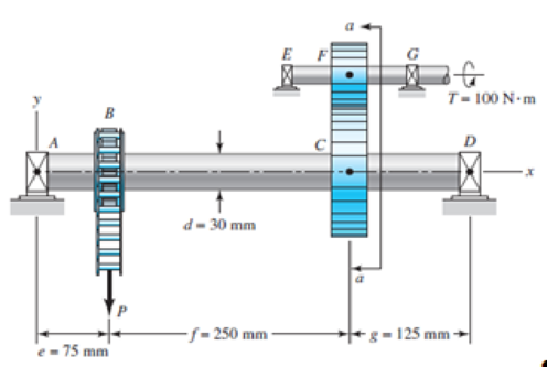
3-77* A torque T = 100 N · m is applied to the shaft EFG, which is running at constant speed and contains gear F. Gear F transmits torque to shaft ABCD through gear C, which drives the chain sprocket at B, transmitting a force P as shown. Sprocket B, gear C, and gear F have pitch diameters of a = 150, b = 250, and c = 125 mm, respectively. The contact force between the gears is transmitted through the pressure angle ϕ = 20°. Assuming no frictional losses and considering the bearings at A, D, E, and G to be simple supports, locate the point on shaft ABCD that contains the maximum tensile bending and maximum torsional shear stresses. Combine these stresses and determine the maximum principal normal and shear stresses in the shaft.
Want to see the full answer?
Check out a sample textbook solution
Chapter 11 Solutions
Shigley's Mechanical Engineering Design (McGraw-Hill Series in Mechanical Engineering)


- The worm shaft shown in the figure transmits 1-kW at 500 rev/min. A static forceanalysis results are also shown in the figure. Bearing A is to be an angular-contact ballbearing mounted to take the 2.75 kN thrust load. The bearing at B is to take only theradial load, so a straight roller bearing will be employed. Use an application factor of1.2, a desired life of 25 kh, and a combined reliability goal of 0.99. (a)Specify each bearing by giving all required charecteristics. (b) Determine the radial and thrust components of loads on each bearing. (c) Make a design assessment for each bearing and of the system.arrow_forwardThe figure shows a shaft mounted in bearings at A and D and having pulleys at B and C. The forces shown acting on the pulley surfaces represent the belt tensions. The shaft is to be made of AISI 1035 CD steel. Using distortion-energy theory with a design factor of 2, determine the minimum shaft diameter to avoid yielding.arrow_forwardA Self-aligning medium series bearing for bores of 85 mm is operating at 300 r.p.m for an average life of 9 years at 10 hours per day, is acted by a 15 kN radial load and 10 kN thrust load. The bearing is subjected to a light shock load and the inner ring is sationary. Determine the suitable self-aligning bearing. Mention the advantage of using self align bearing.arrow_forward
- The following shaft, having a diameter of 20 mm, is made of steel (Sut = 520 MPa, Se = 260 MPa) and is subjected to a fully reversed transverse force F = 120 N and a fully reversed torque T = 60 N.m. The shaft is fixed at its left end. Find the factor of safety at A for infinite lifetime using the modified Goodman diagram.arrow_forwardA bearing is subjected to a radial force of 8kN and a thrust force of 3 kN. Thevalues of X and Y factors are 0.56 and 1.5 respectively. The shaft rotates at 1200 RPM. The diameter of the shaft is 75mm and Bearing no. 6315 (C= 112000N) is selected for this application. Estimate the life of this bearing with 90% reliability.arrow_forwardRead the question carefully and give me all right solutions. Internal torque at rod 1 (kip-ft) Magnitude of shear at rod 2 & 3(ksi) Rotation angle at rod 1 (deg) Rotation angle at flange C (deg)arrow_forward
- The disc clutch of an automobile is carried on a 2-inch 6-splined shaft and not to slide under load. The nominal dimensions are as follows: b = 0.25 D; t = 0.075 D and d = 0.85 D. The hub length of 150 % of shaft diameter. Determine the total horsepower transmitted at 3,600 rpm, if the yield strength of the shaft is 1,400 psiarrow_forwardA steel shaft 3 m long is transmitting 1 MW at 240 rev/min. The working conditions to be satisfiedby the shaft are: (a) the shaft must not twist more than 0.02 radian on a length of 10 diameters.(b) the working stress must not exceed 60 MN/m2. If the modulus of rigidity of steel is 80 GN/m2. what is: (i) the diameter of the shaft required.(ii)the actual working stress. (iii) the angle of twist of the 3 m length.[Ans: 150 mm; 60 MN/m2 ; 0.030 rad]arrow_forwardTorque in = 40nm Holding torque out = 896nm 8.Using your answers from the gear box above, and given that the input shaft has a diameter of 12 mm and the output shaft has a diameter of 15 mm, both shafts are made from aluminium. When this transmission system was operated, it failed. Identify the position where the failure occurred and the reason for this failure. Suggests improvements to the system to overcome the failure mode. The shear strength of aluminium is 207 MPa.arrow_forward
- An engine of a motor vehicle with a wheel diameter of 712 mm develops 50 kW at 2,000 rpm combined efficiencyof the differential and transmission is 75% with an over-all speed reduction to. 1 determine he torque to bedelivered by the clutch N-m.arrow_forwardFlat Belts. Two shafts 10 ft apart, with axes in the same horizontal plane, are to be connected with a flat belt in which the driving pulley, powered by an electrical motor with a 25 hp rating at 900 rev/min, drives the second shaft at half its angular speed. The driven shaft drives uniform (smooth) machinery loads. Select a flat belt.arrow_forwardA vertical shaft is supported by two deep groove ball bearings as shown below. The shaft will be driven by vee belts through a pulley. The combined tensions of the belt apply and the weight of the pulley assembly applies a force of 5.4kN and 900N respectively. The shaft has a diameter of 32mm. Bearing A at the top supports the shaft radially whereas bearing B at the bottom supports the shaft axially and radially. Two deep groove ball bearings have been selected for this application. The models of the bearings are SKF 6305 and SKF 6205 for bearing A and B respectively. a) What are the forces at bearing A and B? b) Paste a screenshot of the graph showing the distribution of the forces in the shaft. c) From the report, find the static load capacity for: Bearing A Bearing Barrow_forward
 Elements Of ElectromagneticsMechanical EngineeringISBN:9780190698614Author:Sadiku, Matthew N. O.Publisher:Oxford University Press
 Mechanics of Materials (10th Edition)Mechanical EngineeringISBN:9780134319650Author:Russell C. HibbelerPublisher:PEARSON
 Thermodynamics: An Engineering ApproachMechanical EngineeringISBN:9781259822674Author:Yunus A. Cengel Dr., Michael A. BolesPublisher:McGraw-Hill Education
 Control Systems EngineeringMechanical EngineeringISBN:9781118170519Author:Norman S. NisePublisher:WILEY
 Mechanics of Materials (MindTap Course List)Mechanical EngineeringISBN:9781337093347Author:Barry J. Goodno, James M. GerePublisher:Cengage Learning
 Engineering Mechanics: StaticsMechanical EngineeringISBN:9781118807330Author:James L. Meriam, L. G. Kraige, J. N. BoltonPublisher:WILEY