
Videos
The worm shaft shown in part a of the figure transmits 1.2 hp at 500 rev/min. A static force analysis gave the results shown in part b of the figure. Bearing A is to be an angular-contact ball bearing selected from Table 11-2, mounted to take the 555-lbf thrust load. The bearing at B is to take only the radial load, so an 02-series cylindrical roller bearing from Table 11-3 will be employed. Use an application factor of 1.2, a desired life of 30 kh, and a combined reliability goal of 0.99, assuming distribution data from manufacturer 2 in Table 11-6. Specify each bearing.
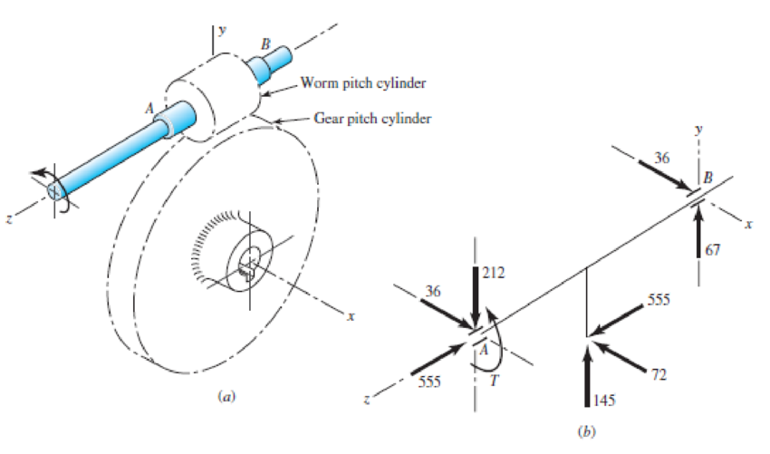
Problem 11-35,
(a) Worm and worm gear, (b) force analysis of worm shaft, forces in pounds.
Want to see the full answer?
Check out a sample textbook solution
Chapter 11 Solutions
Shigley's Mechanical Engineering Design (McGraw-Hill Series in Mechanical Engineering)


- 6. Design a clamp coupling for transmitting 36 kW, at 200 rpm. Allowable shear stress in shaft is 45 MPa, allowable shear stress in key is 40 MPa, and allowable crushing stress in key is 90 MPa. The number of bolts joining the two halves is 4. The permissible tensile stress in bolts is 60 MPa. The coefficient of friction between the muff and shaft can be taken as 0.25arrow_forward5. Design a sleeve coupling for the transmission of 12 kW at 300 rpm by two connected steel shafts. Take service factor KS 1.25. The sleeve is made of CI. The key and the shaft are made of the same material. Allowable stress: Shear stresses in key and shaft 50 MPa Crushing stress in key= 100 MPa Shear stress in CI sleeve = 10 MPaarrow_forwardThe layout of transmission shaft carrying two pulleys B and C and supported on bearings A and D is shown in Figure below. Power is supplied to the shaft by means of a vertical belt on pulley B, that is then transmitted to pulley C carrying a horizontal belt. The maximum tension in belt on pulley B is 2.5 kN. The angle of wrap for both the pulleys is 180o and the coefficient of friction 0.24. The shaft is made of plain carbon steel 30C8 (Syt=400 N/mm2) and the factor of safety is 3. Determine the shaft diameter on strength basis.arrow_forward
- A 15KW and 1200r.p.m motor drives a compressor at 300r.p.m through a pair of spur gears having 20° stub teeth .the centre to centre distance between the shafts is 400mm.the motor pinion is made to forged steel having an allowable static stress 210MPa while the gear is made of cast steel having an allowable static stress as 140MPa.Assuming that the drive operates 8 to 10 hours per day under light shock conditions,find from the standpoint of strength (a) Module;(b)face width and (c)number of teeth an pitch circle diameter of each gear.check the gears thus designed from the consideration of wear .the surface endurance limit may be taken as 700MPa.arrow_forwardThe solid steel rotating shaft in the figure is supported at B and C, and is driven by a gear, not seen, which is linked to spur gear D which has a pitch diameter of 150 mm. The drive gear force F acts at a pressure angle of 20 degrees. The shaft transmits a torque to point A of Ta-350 N.m. The properties of machined steel shaft are Sy-420 MPa and Sut-560MPa. Use a safety factor of 2.5 and determine the minimum allowable diameter in section B and C. Assume sharp felt radii at the bearing shoulders to estimate the stress concentration factors.Explain.arrow_forward.........A shaft rotating at 150 rpm is subjected to variable load: 8 kN during 60% of the time and 2 kN during 40% of the time. Calculate the basic dynamic load rating in kN for the roller bearing (k = 10/3) for 7200 hours of operation with not more than 10% failures.arrow_forward
- The motor shown in the figure supplies 16.5 kW at 1540 rpm at A. Shafts (1) and (2) are each solid 28 mm diameter shafts. Shaft (1) is made of an aluminum alloy [ G=26 GPa], and shaft (2) is made of bronze [ G=45 GPa]. The shaft lengths are L1=3.3m and L2=2.9m, respectively. Gear B has 56 teeth, and gear C has 97 teeth. The bearings shown permit free rotation of the shafts. Determine: the rotation angle of gear D with respect to flange A. [Answer φD/A = 0.314 rad]arrow_forwardA 1.5 in diameter 10-spline shaft and permanent fit has a compressive force of 2000 lbs. Find the torque applied if hub length 2 in.arrow_forwardA 6-in-wide polyamide F-1 flat belt is used to connect a 4-in-diameter pulley to drive a larger pulley with an angular velocity ratio of 3. The center-to-center distance is 8 ft. The angular speed of the small pulley is 1850 rev/min as it delivers 2 hp. The service is such that a service factor Ks of 1.25 is appropriate. (a) Find Fc, Fi, F1a, and F2. (b) Find Ha, nfs, and belt length. (c) Find the dip.arrow_forward
- Write legibly, provide manual step by step solution, and diagram for below given problem. A 2.5 in diameter 10 spline shaft ( d= 0.86D, w= 0.156D, h= 0.07D ) to slide when not under load has a compressive force of 2500 lb. Find the torque applied if hub length is 1 1/2 in. Ans. 2906.25 in-lbarrow_forwardA plate clutch has 3 discs on the driving shaft and 2 discs on the driven shaft, providing four pairs of contact surfaces. The outside diameter of the contact surfaces is 240 mm and inside diameter 120 mm. Assuming uniform pressure and coeff. Of friction is 0.3. Find the total spring load pressing the plates together to transmit 23kw power at 1475 revolution per minute. If there 6 springs each of stiffness 13 kN/m and each of the contact surfaces has worn away by 1.25 mm. find the maximum power that can be transmitted assuming uniform wear. A plate clutch has 3 discs on the driving shaft and 2 discs on the driven shaft, providing four pairs of contact surfaces. The outside diameter of the contact surfaces is 240 mm and inside diameter 120 mm. Assuming uniform pressure and coeff. Of friction is 0.3. Find the total spring load pressing the plates together to transmit 23kw power at 1475 revolution per minute. If there 6 springs each of stiffness 13 kN/m and each of the contact surfaces…arrow_forwardWrite legibly, provide manual step by step solution, and diagram for below given problem. A 2 in diameter 6-spline shaft ( d= 0.85D, W= 0.25D, h= 0.075D ) and to slide when not under load has a compressive force of 2500 lbs. Find the torque applied if hub length is 2 1/2 in Ans. 2312.5 in-lbarrow_forward
 Elements Of ElectromagneticsMechanical EngineeringISBN:9780190698614Author:Sadiku, Matthew N. O.Publisher:Oxford University Press
 Mechanics of Materials (10th Edition)Mechanical EngineeringISBN:9780134319650Author:Russell C. HibbelerPublisher:PEARSON
 Thermodynamics: An Engineering ApproachMechanical EngineeringISBN:9781259822674Author:Yunus A. Cengel Dr., Michael A. BolesPublisher:McGraw-Hill Education
 Control Systems EngineeringMechanical EngineeringISBN:9781118170519Author:Norman S. NisePublisher:WILEY
 Mechanics of Materials (MindTap Course List)Mechanical EngineeringISBN:9781337093347Author:Barry J. Goodno, James M. GerePublisher:Cengage Learning
 Engineering Mechanics: StaticsMechanical EngineeringISBN:9781118807330Author:James L. Meriam, L. G. Kraige, J. N. BoltonPublisher:WILEY