
Concept explainers
Videos
A 16-tooth pinion drives the double-reduction spur-gear train in the figure. All gears have 25° pressure angles. The pinion rotates ccw at 1200 rev/min and transmits power to the gear train. The shaft has not yet been designed, but the free bodies have been generated. The shaft speeds are 1200 rev/min, 240 rev/min, and 80 rev/min. A bearing study is commencing with a 10-kh life and a gearbox bearing ensemble reliability of 0.99, assuming distribution data from manufacturer 2 in Table 11-6. An application factor of 1.2 is appropriate. For each shaft, specify a matched pair of 02-series cylindrical roller bearings from Table 11-3.
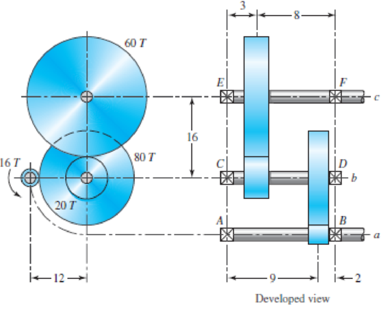
(a)
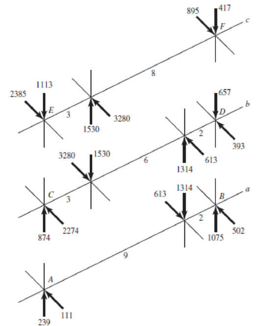
(b) Developed view
Problem 11–37
(a) Drive detail; (b) force analysis on shafts. Forces in pounds; linear dimensions in inches.
Want to see the full answer?
Check out a sample textbook solution
Chapter 11 Solutions
Shigley's Mechanical Engineering Design (McGraw-Hill Series in Mechanical Engineering)


- The reducer input shaft shown in the figure is taperedIt transmits moment with the help of a gear wheel.On the spindle, Fa = 552 N, Fr = 457 N, Ft = 1960 Nfrom gear forces and belt mechanismincoming Fk = 2600 N radial force impact. The shaft rotates with n = 1090 rpm.Accept the shaft diameter in the A bearing as dA = 35 mm.Fixed ball bearing for Lh = 13500 hselectarrow_forwardThe figure shows a double-reduction helical gearset. Pinion 2 is the driver, and it receives a torque of 1200 Ibf • in from its shaft in the direction shown. Pinion 2 has a normal diametral pitch of 8 teeth/in, 14 teeth, and a normal pressure angle of 20° and is cut right-handed with a helix angle of 30°. The mating gear 3 on shaft b has 36 teeth. Gear 4, which is the driver for the second pair of gears in the train, has a normal diametral pitch of 3 teeth/in, 15 teeth, and a normal pressure angle of 20° and is cut left-handed with a helix angle of 15°. Mating gear S has 45 teeth. Find the magnitude and direction of the force exerted by the bearings C and D on shaft b if bearing C can take only a radial load while bearing D is mounted to take both radial and thrust loads.arrow_forwardShaft a in the figure has a power input of 75 kW at a speed of 1000 rev/min in the counterclockwise direction. The gears have a module of 5 mm and a 20° pressure angle. Gear 3 is an idler (b) Find the torque T4c that gear 4 exerts on shaft c.arrow_forward
- A pair of straight-tooth bevel gears (as shown in the figure above) are in mesh transmitting 35 hp at 1000 rpm (pinion speed). The gear rotates at 400 rpm. The gear system has a pitch of 6 and a 20-degree pressure angle. The face width is 2 inches and the pinion has 36 teeth. Determine the tangential, radial, and axial forces acting on the pinionarrow_forwardA 15 kW and 1200 motor drives a compressor at 300 a pair of spur gears having . The center-to-center distance between the shafts is 400 . The motor pinion is made of forged steel having an allowable static stress as 210 MPa, while the gear is made of cast steel having allowable static stress as 140 MPa . Assuming that the drive operates 8 to 10 hours per day under light conditions , find from the standpoint of strength Module , 2. Fare and 3. Number of teeth and pitch circle diameter of each gear 2. Check the gears thus designed from the consideration of Static tooth load or endurance strength of the tooth flexural endurance limil (sigma_{\epsilon}) may be taken as 400 MPa 3. Check the gears thus designed from the consideration of wear surface endurance limit ( sigma epsilon x ) may be taken 700 MPa b ^ pi ( 6.154 - 0512/pi; F_{N}arrow_forwardA 15 kW and 1200 r.p.m. motor drives a compressor at 300 r.p.m. through a pair of spur gears having 20° stub teeth. The centre to centre distance between the shafts is 400 mm. The motor pinion is made of forged steel having an allowable static stress as 210 MPa, while the gear is made of cast steel having allowable static stress as 140 MPa. Assuming that the drive operates 8 to 10 hours per day under light shock conditions, find from the standpoint of strength, 1. Module; 2. Face width and 3. Number of teeth and pitch circle diameter of each gear. Check the gears thus designed from the consideration of wear. The surface endurance limit may be taken as 700 MPaarrow_forward
- The double-reduction helical gearset shown in the figure is driven through shaft a at a speed of 700 rev/min. Gears 2 and 3 have a normal diametral pitch of 12 teeth/in, a 30° helix angle, and a normal pressure angle of 20°. The second pair of gears in the train, gears 4 and 5, have a normal diametral pitch of 8 teeth/in, a 25° helix angle, and a normal pressure angle of 20°. The tooth numbers are: N, = 12, N, = 48, N4 = 16, N, = 36. Find: (a) The directions of the thrust force exerted by each gear upon its shaft (b) The speed and direction of shaft c (c) The center distance between shaftsarrow_forward13–31 Shaft a in the figure has a power input of 75 kW at a speed of 1000 rev/min in the counterclockwise direction. The gears have a module of 5 mm and a 20° pressure angle. Gear 3 is an idler.(a) Find the force F3b that gear 3 exerts against shaft b.arrow_forwardThe reducer input shaft shown in the figure is tapered It transmits moment with the help of a gear wheel. On the spindle, Fa = 552 N, Fr = 457 N, Ft = 1960 N from gear forces and belt mechanism incoming Fk = 2600 N radial force impact . The shaft rotates with n = 1090 rpm. Accept the shaft diameter in the A bearing as dA = 35 mm. Fixed ball suitable for Lh = 13500 h select bearing.arrow_forward
- The top half of a compound Epicyclic gearset is shown in Figure, with input shaft I rotating at a constant speed of 700 rpm in a clockwise direction and generating 12 kW input power. The Annulus wheel A2 isform a compound wheel with gear O and connected to an auxiliary gear N on shaft X. . The Annulus A1 rotates in a counter-clockwise direction at a speed of 5,300 rpm. Calculate the following using this condition: The speed and direction of output shaft O (NO), shaft X (NX) and gear ratio (n). If Annulus wheel A1 is locked calculate the speed and direction of output shaft O (NO), shaft X (NX) and gear ratio (n). The braking torque (Tb) (magnitude and direction) that must be applied to Annulus wheel A1 to hold it stationary, assuming gear transmission efficiency is 90%. Number of gear teeth:P1 = 30 , A1 = 120P2 = 50 , A2 = 140N = 60 , O = 120arrow_forwardA pair of gray iron and steel helical gears, having a helix angle of 15° with 20° full-depth teeth are to transmit 10 hp at 1500 rpm of a 4-in pinion having a total number of 28teeth. The velocity ratio desired is about mw = 4. Find the (a) normal circular pitch, (b) normal diametral pitch, (c) axial pitch, and (d) dynamic loadarrow_forwardIn a gear set, a 36-tooth spur pinion drives a 60-tooth spur gear. The teeth of these gear are cast iron profile. The diametral pitch is 6-teeth/in, the face width si 0.5 inches, and the pressure angle is 20 degrees. Assume that the pinion transmits 10 hp at a speed of 2000 rpm. Find the tangential load in lbf Find the contact stress in kpsi, assuming CP=1960 psi.arrow_forward
 Elements Of ElectromagneticsMechanical EngineeringISBN:9780190698614Author:Sadiku, Matthew N. O.Publisher:Oxford University Press
 Mechanics of Materials (10th Edition)Mechanical EngineeringISBN:9780134319650Author:Russell C. HibbelerPublisher:PEARSON
 Thermodynamics: An Engineering ApproachMechanical EngineeringISBN:9781259822674Author:Yunus A. Cengel Dr., Michael A. BolesPublisher:McGraw-Hill Education
 Control Systems EngineeringMechanical EngineeringISBN:9781118170519Author:Norman S. NisePublisher:WILEY
 Mechanics of Materials (MindTap Course List)Mechanical EngineeringISBN:9781337093347Author:Barry J. Goodno, James M. GerePublisher:Cengage Learning
 Engineering Mechanics: StaticsMechanical EngineeringISBN:9781118807330Author:James L. Meriam, L. G. Kraige, J. N. BoltonPublisher:WILEY