
Videos
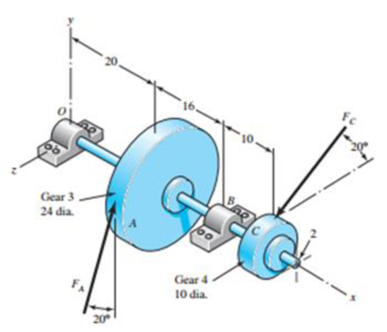
The figure shown is a geared countershaft with an overhanging pinion at C. Select an angular-contact ball bearing from Table 11-2 for mounting at O and an 02-series cylindrical roller bearing from Table 11-3 for mounting at B. The force on gear A is FA = 600 lbf, and the shaft is to run at a speed of 420 rev/min. Solution of the statics problem gives force of bearings against the shaft at O as RO = −387j + 467k lbf, and at B as RB = 3l6j − 1615k lbf. Specify the bearings required, using an application factor of 1.2, a desired life of 40 kh, and a combined reliability goal of 0.95, assuming distribution data from manufacturer 2 in Table 11-6.
Problem 11-32
Dimensions in inches.
Want to see the full answer?
Check out a sample textbook solution
Chapter 11 Solutions
Shigley's Mechanical Engineering Design (McGraw-Hill Series in Mechanical Engineering)


- A steel shaft 800 mm long transmitting 15 kW at 400 r.p.m. is supported at two bearings at the twoends. A gear wheel having 80 teeth and 500 mm pitch circle diameter is mounted at 200 mm from theleft hand side bearing and receives power from a pinion meshing with it. The axis of pinion and gearlie in the horizontal plane. A pulley of 300 mm diameter is mounted at 200 mm from right hand sidebearing and is used for transmitting power by a belt. The belt drive is inclined at 30° to the vertical inthe forward direction. The belt lap angle is 180 degrees. The coefficient of friction between belt andpulley is 0.3. Design and sketch the arrangement of the shaft assuming the values of safe stresses as :τ = 55 MPa; σt= 80 MPa. Take torsion and bending factor 1.5 and 2 respectively.arrow_forwardThe worm shaft shown in the figure transmits 1-kW at 500 rev/min. A static forceanalysis results are also shown in the figure. Bearing A is to be an angular-contact ballbearing mounted to take the 2.75 kN thrust load. The bearing at B is to take only theradial load, so a straight roller bearing will be employed. Use an application factor of1.2, a desired life of 25 kh, and a combined reliability goal of 0.99. (a)Specify each bearing by giving all required charecteristics. (b) Determine the radial and thrust components of loads on each bearing. (c) Make a design assessment for each bearing and of the system.arrow_forward13-32 The 247 6-pitch 20° pinion 2 shown in the figure rotates clockwise at 1000 rev/min and is driven at a power of 25 hp. Gears 4, 5, and 6 have 24, 36, and 144 teeth, respectively. What torque can arm 3 deliver to its output shaft? Draw free-body diagrams of the arm and of each gear and show all forces that act upon them.arrow_forward
- 2. A shaft is supported on bearings A and B, 800 mm between centres. A 20 degrees straight tooth spur gear having 600 mm pitch diameter, is located 200 mm to the right of the left hand bearing A, and a 700 mm diameter pulley is mounted 250 mm towards the left of bearing B. The gear is driven by a pinion with a downward tangential force while the pulley drives a horizontal belt having 180 degrees angle of wrap. The pulley also serves as a flywheel and weighs 2000 N. The maximum belt tension is 3000 N and the tension ratio is 3: 1. Determine the maximum bending moment and the necessary shaft diameter if the allowable shear stress of the material is 40 MPa.arrow_forwardSelect an angular contact ball bearing to carry a radial load of 336lb at a shaft speed of 1800 rpm for 5500 hours. Anapplicationfactorof1.2isappropriate. Use a reliability of 96%.arrow_forward6. Design a clamp coupling for transmitting 36 kW, at 200 rpm. Allowable shear stress in shaft is 45 MPa, allowable shear stress in key is 40 MPa, and allowable crushing stress in key is 90 MPa. The number of bolts joining the two halves is 4. The permissible tensile stress in bolts is 60 MPa. The coefficient of friction between the muff and shaft can be taken as 0.25arrow_forward
- A single deep grove ball bearing series 3, the outer ring rotates at 1500 rpm with little shock load. Bearing has a bore diameter of 45 mm, working with a load 1890 lb radial and 1250 lb axial load. Determine the rated life and median life of the bearing. Use the design factors according to the attached table.arrow_forwardThe picture shows the rear swivel axle bearing design of a 4-wheel wagon. It is known that the speed of the wagon wheels is n = 37 rpm. The total radial load carried by the wagon is given as Fr= 16060 Newtons. In addition, due to road conditions, Fa axial load is applied to the wagon. If the axial load on the A bearing is 10% of the radial (vertical) load on this bearing, calculate the dynamic load number (C) of the bearing in the A bearing in Newtons for 18616 hours of life. fo*Fa/Co = 0.345 Pi=3.14arrow_forwardA Self-aligning medium series bearing for bores of 85 mm is operating at 300 r.p.m for an average life of 9 years at 10 hours per day, is acted by a 15 kN radial load and 10 kN thrust load. The bearing is subjected to a light shock load and the inner ring is sationary. Determine the suitable self-aligning bearing. Mention the advantage of using self align bearing.arrow_forward
- In a particular application, the radial load acting on a ball bearing is 5 kN and the expected life for 90% of the hearings is 8000 Calculate the dynamic load carrying capacity of the bearing, when the shaft rotates at 1450 rpm.arrow_forwardb) Design a single row deep groove ball bearing with basic dynamic load rating of 33 KN to be used in a turbine to carry a radial load of 1584 N. The expected life of the bearing is 5591 hours at 529 rpm. Take k=3 for all types of ball bearings. Take the value of the shock load factor as 1.8. The radial and axial load factors are 1.3 and 1.6 respectively and the rotational factor is 1. Calculate: i) Expected life of bearings in millions of revolutions ii) Design equivalent dynamic load in N iii) Basic equivalent dynamic load in N iv) Axial load acting on the bearing in Narrow_forwardi) Explain the static rating of rolling contact bearings. ii) Write any three technical reasons why ball and roller bearings need to be lubricated. b) Design a self-aligning ball bearing to be used in a turbine to carry a combined radial load of 4466 N and thrust load of 1420 N. The basic dynamic load rating of the bearing is 31 kN at 547 rpm. Take k=3 for all types of ball bearings. Take the value of the shock load factor as 1.3. The axial and radial load factors are 1.8 and 1.2 respectively and the rotational factor is 1. Calculate: i) Basic equivalent dynamic load in N ii) Design equivalent dynamic load in N iii) Expected life of bearings in hoursarrow_forward
 Elements Of ElectromagneticsMechanical EngineeringISBN:9780190698614Author:Sadiku, Matthew N. O.Publisher:Oxford University Press
 Mechanics of Materials (10th Edition)Mechanical EngineeringISBN:9780134319650Author:Russell C. HibbelerPublisher:PEARSON
 Thermodynamics: An Engineering ApproachMechanical EngineeringISBN:9781259822674Author:Yunus A. Cengel Dr., Michael A. BolesPublisher:McGraw-Hill Education
 Control Systems EngineeringMechanical EngineeringISBN:9781118170519Author:Norman S. NisePublisher:WILEY
 Mechanics of Materials (MindTap Course List)Mechanical EngineeringISBN:9781337093347Author:Barry J. Goodno, James M. GerePublisher:Cengage Learning
 Engineering Mechanics: StaticsMechanical EngineeringISBN:9781118807330Author:James L. Meriam, L. G. Kraige, J. N. BoltonPublisher:WILEY