
Concept explainers
Videos
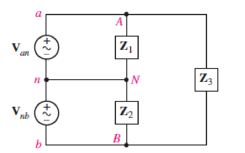
The single-phase three-wire system of Fig. 12.31 has three separate load impedances. If the source is balanced and Van = 110 +j0 V rms, (a) express Van and Vbn in phasor notation. (b) Determine the phasor voltage which appears across the impedance Z3. (c) Determine the average power delivered by the two sources if Z1 = 50 + j0 Ω, Z2 = 100 + j45 Ω, and Z3 = 100 – j90 Ω. (d) Represent load Z3 by a series connection of two elements, and state their respective values if the sources operate at 60 Hz.
(a)
The expression of phase to neutral voltage of phase
Answer to Problem 11E
The expression of phase to neutral voltage of phase
Explanation of Solution
Given data:
The phase to neutral voltage of phase
Calculation:
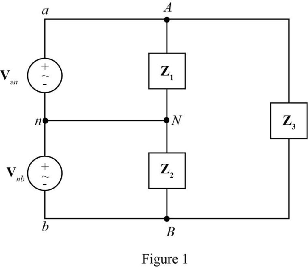
The given diagram is shown in Figure 1.
The general expression for the phasor notation is given by,
Here,
The magnitude of
Here,
The angle measured from the reference
Substitute
Substitute
Substitute
The voltage
The voltage
Substitute
Substitute
Conclusion:
Therefore, the expression of phase to neutral voltage of phase
(b)
The phasor voltage which appears across the impedance
Answer to Problem 11E
The phasor voltage which appears across the impedance
Explanation of Solution
Calculation:
The voltage across the impedance
The voltage across the impedance
The voltage across the impedance
The voltage across the impedance
Substitute
Conclusion:
Therefore, the phasor voltage which appears across the impedance
(c)
The average power delivered by the two sources.
Answer to Problem 11E
The average power delivered by source
Explanation of Solution
Given data:
The value of the impedance
The value of the impedance
The value of the impedance
Calculation:
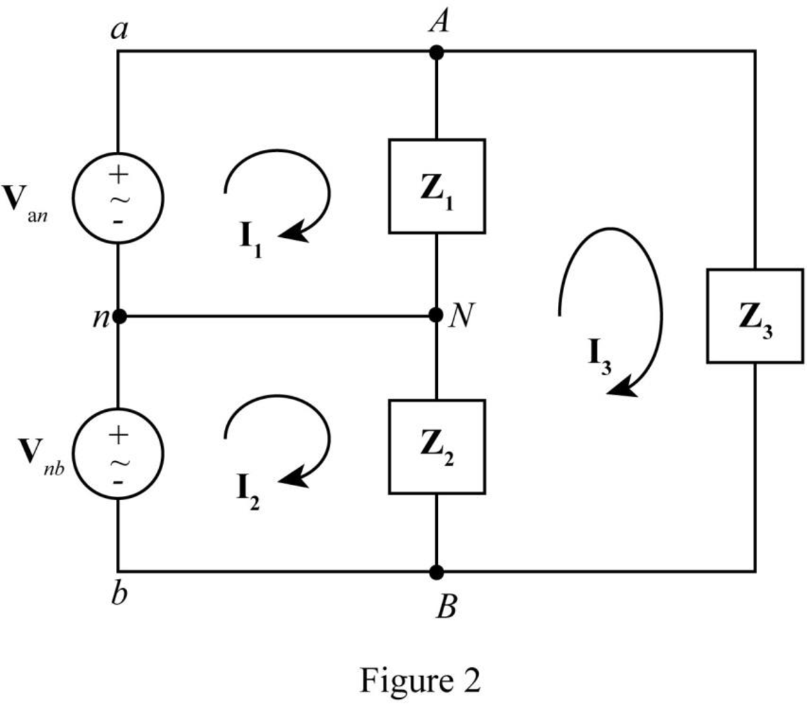
The required diagram is shown in Figure 2.
The formula to find current
Substitute
Substitute
Substitute
Substitute
The formula to find current
Substitute
Substitute
Substitute
Substitute
The formula to find current
Substitute
The power
Substitute
The power
Substitute
Conclusion:
Therefore, the average power delivered by source
(d)
The representation of load
Answer to Problem 11E
The impedance
Explanation of Solution
Given data:
The operating frequency is
Calculation:
The value of the impedance
The real part of
Hence, the resistance
The imaginary part of
Hence, The series capacitive reactance
Here,
Substitute
Conclusion:
Therefore, the impedance
Want to see more full solutions like this?
Chapter 12 Solutions
Loose Leaf for Engineering Circuit Analysis Format: Loose-leaf


- Figure 2.33 gives the general -Y transformation. (a) Show that the general transformation reduces to that given in Figure 2.16 for a balanced three-phase load. (b) Determine the impedances of the equivalent Y for the following impedances: ZAB=j10,ZBC=j20, and ZCA=j25. ZAB=ZAZB+ZBAC+ZCZAZCZA=ZABZCAZAB+ZBC+ZCAZBC=ZAZB+ZBAC+ZCZAZAZB=ZABZBCZAB+ZBC+ZCAZCA=ZAZB+ZBAC+ZCZAZBZA=ZCAZBCZAB+ZBC+ZCAarrow_forwardA star-connected three-phase balanced power system A transmission line with line impedance Zh It feeds an unbalanced three-phase delta load. Regarding line and load impedances values are given. Zh=2+j, Z1=40+j20, Z2=50-j30 and Z3=25 Accordingly; a)- Calculate IAB and IAC phase currents. b)- Calculate the line currents IAave IBb.arrow_forwardA balanced delta-connected load has phase impedances of 4+j3 Ohms. It is connected to balanced transmission lines, with Vab = 1.5kV @ 15 degrees. a) What is the current through each of the load phases? b) What is the current through each of the transmission lines? c) Which ACSR cable should be used for these transmission lines to give a 20% current rating margin for this load?arrow_forward
- The phase voltage at the terminals of a balanced three-phase Yconnected load is 2400 V. The load has an impedance of 16 + j12 Ω/ϕ and is fed from a line having an impedance of 0.10 + j0.80 Ω/ϕ. The Yconnected source at the sending end of the line has a phase sequence of acb and an internal impedance of 0.02 + j0.16 Ω/ϕ. Use the a-phase voltage at the load as the reference and calculate (a) the line currents IaA, IbB, and IcC; (b) the line voltages at the source, Vab, Vbc, and Vca; and (c) the internal phase-to-neutral voltages at the source, Va ′n, Vb′n, and Vc′n.arrow_forwardA balanced, positive-sequence, Y-connected voltage source with Eab = 480∠0o volts is applied to abalanced-∆ load with Z∆ = 30 ∠40o Ω. The line impedance between the source and load is ZL = 1 ∠850 Ω.for each phase. Calculate the line currents, the ∆ -load currents, and the voltages at the load terminals.Recall that ZY = Z∆/3arrow_forwardA Y-Y three-phase system has a source of 380 V and a load of impedance of 6+j5 Ohm/phase through a transmission line of 2+j 1 Ohm/phase.Plot this Y-Y three-phase system then calculate complex power supplied by the source.arrow_forward
- The length of a three-phase power transmission line with a nominal operating voltage of 69 kV is 16km. The impedance of the transmission line per unit length is 0.125 + j0.4375 ohm/ km. At the end of the line, a 70 MVA star connected load with a power factor of 0.8 back under 69 kV interphase voltage is fed. Capacitive circuit element with a capacitance of 19.14 mikro F / phase is placed as shunt at the end of the transmission line. According to these given; a) Line head voltage and current, b) Calculate the active and reactive power per line.arrow_forwardA short 3-phase transmission line connected to a 33kV, 50 Hz generating station at the sending end is required to supply a load of 10 MW at 0·8 lagging power factor at 30 kV at the receiving end. If the minimum transmission efficiency is to be limited to 96%, estimate the per phase value of resistance and inductance of the line. [2·4 Ω; 0·028 H]arrow_forwardA 4200-V, three-phase transmission line has an impedance of 4+j ohms per phase. If it supplies a load of 1 MVA at 0.75 power factor, find: (a) the complex power (b) the power loss in the line (c) the voltage at the sending end. *Ans. S=0.75+j0.66 MVA, PL=25.14 kW and VS=4.492∠ − 1.912°kV Use four decimal places.arrow_forward
- In a balanced 3-phase system, the effective value of the IbB current for a triangular connected load is known as 15 (-150 degrees) Amperes and the effective value of the VCA voltage is known as 60 (90 degrees) Volts. Since it is known that the phase sequence is positive; Phase current IAB= 8.660 (60 degrees) A Phase current IAC= [Select ] Load impedance Z= [Select ] the total average power sent to the 3 phase load is Pt Aggregate= [Select ] (Note: Perform your operations using at least 3 digits after the comma.)arrow_forwardA 3-phase Y-connected load draws power from a 3-phase Y-connected source. The source voltage, ?=440∠0º?_rms and the load impedance, Z_y=(30+j15) Ω. The line impedance, Z_line= (1+j1)Ω and the system operates at 60 Hz. a) Draw the single-phase equivalent circuit and label all given quantities numerically. b) Calculatethe rms line (phase) current phasor in each phase. c) Calculate the total active or real power supplied by the source. d) Calculate the total active or real power consumed by the load. e) Calculate the total line loss i.e. the total activepower lost due to line. f) Determine the power efficiency of the system.arrow_forwardA load of 135 MW at a power factor of 0.6 lagging can be delivered by a 3-phase transmission line. The voltage at the receiving end is to be maintained at 57 kV and the loss in the transmission is 6.5% of the power delivered. (Consider the line to be a short transmission line) Find A) Single phase Power delivered B) Per phase voltage C) Current flowing through the transmission line D) 3 Phase Losses in the transmission line E) Per phase resistance of the transmission linearrow_forward
 Power System Analysis and Design (MindTap Course ...Electrical EngineeringISBN:9781305632134Author:J. Duncan Glover, Thomas Overbye, Mulukutla S. SarmaPublisher:Cengage Learning