
Loose Leaf for Engineering Circuit Analysis Format: Loose-leaf
9th Edition
ISBN: 9781259989452
Author: Hayt
Publisher: Mcgraw Hill Publishers
expand_more
expand_more
format_list_bulleted
Concept explainers
Videos
Textbook Question
thumb_up100%
Chapter 12.2, Problem 3P
Modify Fig. 12.9 by adding a 1.5 Ω resistance to each of the two outer lines, and a 2.5 Ω resistance to the neutral wire. Find the average power delivered to each of the three loads.
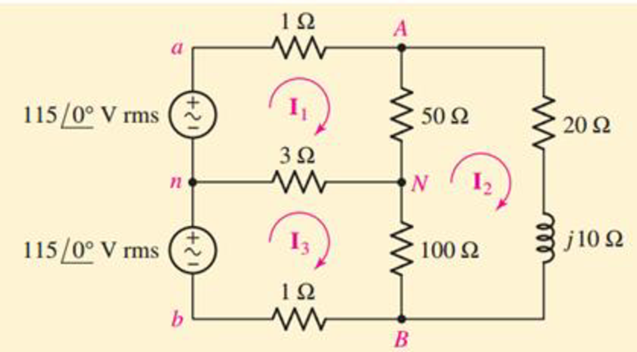
FIGURE 12.9 A typical single-phase three-wire system.
Expert Solution & Answer
Want to see the full answer?
Check out a sample textbook solution
Students have asked these similar questions
A single phase transmission line is delivering 470 kVA load at 14 kV. Its resistance is 4 Ω and inductive reactance is 8 Ω. If the load power factor is 0.9 lagging.
Determine the
1Current through the line:
2Sending end voltage:
3Sending end power factor:
4Regulation of transmission line:
5Efficiency of transmission line:
An overhead 3-phase transmission line delivers 1200 kW at 22 kV at 0.8 power factor lagging.
The length of the line is 25 km. The resistance and reactance of conductor are 0.25 Ω per km
and 0.30 Ω per km.
Determine,
i) Sending end voltage
ii) Percentage regulation
iii) Sending end power factor
iv) Transmission efficiency
A short 3-phase transmission line connected to a 33kV, 50 Hz generating station at the sending end is required to supply a load of 10 MW at 0·8 lagging power factor at 30 kV at the receiving end. If the minimum transmission efficiency is to be limited to 96%, estimate the per phase value of resistance and inductance of the line. [2·4 Ω; 0·028 H]
Chapter 12 Solutions
Loose Leaf for Engineering Circuit Analysis Format: Loose-leaf
Ch. 12.1 - Let and . Find (a) Vad; (b) Vbc; (c) Vcd.Ch. 12.2 - Prob. 2PCh. 12.2 - Modify Fig. 12.9 by adding a 1.5 resistance to...Ch. 12.3 - A balanced three-phase three-wire system has a...Ch. 12.3 - A balanced three-phase three-wire system has a...Ch. 12.3 - Three balanced Y-connected loads are installed on...Ch. 12.4 - Each phase of a balanced three-phase -connected...Ch. 12.4 - Prob. 8PCh. 12.5 - Determine the wattmeter reading in Fig. 12.24,...Ch. 12.5 - Prob. 10P
Ch. 12 - Prob. 1ECh. 12 - Prob. 2ECh. 12 - Prob. 3ECh. 12 - Describe what is meant by a polyphase source,...Ch. 12 - Prob. 5ECh. 12 - Prob. 6ECh. 12 - Prob. 7ECh. 12 - Prob. 8ECh. 12 - Prob. 9ECh. 12 - Prob. 10ECh. 12 - The single-phase three-wire system of Fig. 12.31...Ch. 12 - Prob. 12ECh. 12 - Referring to the balanced load represented in Fig....Ch. 12 - Prob. 14ECh. 12 - Prob. 15ECh. 12 - Consider a simple positive phase sequence,...Ch. 12 - Assume the system shown in Fig. 12.34 is balanced,...Ch. 12 - Repeat Exercise 17 with Rw = 10 , and verify your...Ch. 12 - Prob. 19ECh. 12 - Prob. 20ECh. 12 - Prob. 21ECh. 12 - Prob. 22ECh. 12 - A three-phase system is constructed from a...Ch. 12 - Prob. 24ECh. 12 - Each load in the circuit of Fig. 12.34 is composed...Ch. 12 - Prob. 26ECh. 12 - Prob. 27ECh. 12 - A three-phase load is to be powered by a...Ch. 12 - For the two situations described in Exercise 28,...Ch. 12 - Prob. 30ECh. 12 - Prob. 31ECh. 12 - Prob. 32ECh. 12 - Repeat Exercise 32 if Rw = 1 . Verify your...Ch. 12 - Prob. 34ECh. 12 - Prob. 35ECh. 12 - Prob. 36ECh. 12 - A wattmeter is connected into the circuit of Fig....Ch. 12 - Find the reading of the wattmeter connected in the...Ch. 12 - (a) Find both wattmeter readings in Fig. 12.39 if...Ch. 12 - Circuit values for Fig. 12.40 are , , , , . Find...Ch. 12 - Prob. 41ECh. 12 - Prob. 42ECh. 12 - (a) Is the load represented in Fig. 12.41...Ch. 12 - Prob. 44E
Knowledge Booster


Learn more about
Need a deep-dive on the concept behind this application? Look no further. Learn more about this topic, electrical-engineering and related others by exploring similar questions and additional content below.Similar questions
- Figure 2.33 gives the general -Y transformation. (a) Show that the general transformation reduces to that given in Figure 2.16 for a balanced three-phase load. (b) Determine the impedances of the equivalent Y for the following impedances: ZAB=j10,ZBC=j20, and ZCA=j25. ZAB=ZAZB+ZBAC+ZCZAZCZA=ZABZCAZAB+ZBC+ZCAZBC=ZAZB+ZBAC+ZCZAZAZB=ZABZBCZAB+ZBC+ZCAZCA=ZAZB+ZBAC+ZCZAZBZA=ZCAZBCZAB+ZBC+ZCAarrow_forwardConsider a three-phase Y-connected source feeding a balanced- load. The phasor sum of the line currents as well as the neutral current are always zero. (a) True (b) Falsearrow_forwardA three-phase line with an impedance of (0.2+j1.0)/ phase feeds three balanced three-phase loads connected in parallel. Load 1: Absorbs a total of 150 kW and 120 kvar. Load 2: Delta connected with an impedance of (150j48)/phase. Load 3: 120 kVA at 0.6 PF leading. If the line-to-neutral voltage at the load end of the line is 2000 v (rms), determine the magnitude of the line-to-line voltage at the source end of the line.arrow_forward
- A balanced delta-connected load has phase impedances of 4+j3 Ohms. It is connected to balanced transmission lines, with Vab = 1.5kV @ 15 degrees. a) What is the current through each of the load phases? b) What is the current through each of the transmission lines? c) Which ACSR cable should be used for these transmission lines to give a 20% current rating margin for this load?arrow_forwardQuestion 5: A single-phase transmission line has a resistance of 0.22 ohm and inductive reactance of 0.36 ohm. Find the voltage at the sending end to give 500kva at 2000V at the receiving end at a load power factor of 0.707 lagging. Also find the efficiency of transmission at this load. Subject Power Transmission and Distributionarrow_forwardFor the balanced positive-sequence three-phase circuit below, given that Van=100<10 V and Z=15<55 ohm,calculate: 1. the line currents for phases a, b and c2. the line to line voltages at the loadarrow_forward
- 7. A single phase line is transmitting 1100 kW power to a factory at 11kV and 0.8 p.f lagging. It has a total resistance of 2 Ω and and loop reactance of 3Ω, determine (1) Voltage at sending end (2) Percentage regulation (3) Efficiency of transmission line.arrow_forwardA single phase transmission line is delivering 410 kVA load at 10 kV. Its resistance is 5.5 ohm and inductive reactance is 8 ohm if the load power factor is 0.7 lagging. Determine the Current through the line Sending end voltage Sending end power factor Regulation of transmission line Efficiency of transmission linearrow_forwardThe resistance and reactance of the single-phase 60Hz transmission line conductors are 7.6 ohm and 6.6 ohm respectively. The transmission line delivers 20MW at a power factor of 0.66 lagging to the load with 54kV receiving end voltage. Determine the following a) The inductance of the transmission line in mH b) Sending end power factor c) Percentage voltage regulation d) Percentage Efficiencyarrow_forward
- A balanced delta connected load of 13+j16 ohm per phase is connected at the end of a three-phase line. The line impedance is 2+j11 ohm- per phase. The line is supplied from a three-phase source with a line-to-line voltage of 207.85 Vrms. Taking phase "a" voltage Va as reference, determine the following: (a) Current in phase a. (b) Total complex power supplied from the source. (c) Magnitude of the line-to-line voltage at the load terminal.arrow_forwardA three-phase short transmission line has a per phase impedance of 0.3 + j0.4 Ω The receiving end voltage is 6 351 volts per phase and the voltage regulations is not exceed 5 percent. Calculate the total line loss when it is supplying maximum power. A. 212.08MW B. 7.69MW C. 122.46MW D. 40.81MWarrow_forwarda single phase transmission line is delivering 500kva load at 2kV It resistance 0.2ohm and inductive reactance 0.4ohm. Determine voltage regulation if the load power factor is 0.707 laggingarrow_forward
arrow_back_ios
SEE MORE QUESTIONS
arrow_forward_ios
Recommended textbooks for you
 Power System Analysis and Design (MindTap Course ...Electrical EngineeringISBN:9781305632134Author:J. Duncan Glover, Thomas Overbye, Mulukutla S. SarmaPublisher:Cengage Learning
Power System Analysis and Design (MindTap Course ...
Electrical Engineering
ISBN:9781305632134
Author:J. Duncan Glover, Thomas Overbye, Mulukutla S. Sarma
Publisher:Cengage Learning
How do Electric Transmission Lines Work?; Author: Practical Engineering;https://www.youtube.com/watch?v=qjY31x0m3d8;License: Standard Youtube License