
Concept explainers
Videos
(a) Find both wattmeter readings in Fig. 12.39 if VA = 100∠0 ° V rms, VB = 50∠90° V rms, ZA = 10 − j10 Ω, ZB = 8 + j6 Ω, and ZC = 30 + j10 Ω. (b) Is the sum of these readings equal to the total power taken by the three loads? Verify your answer with an appropriate simulation.
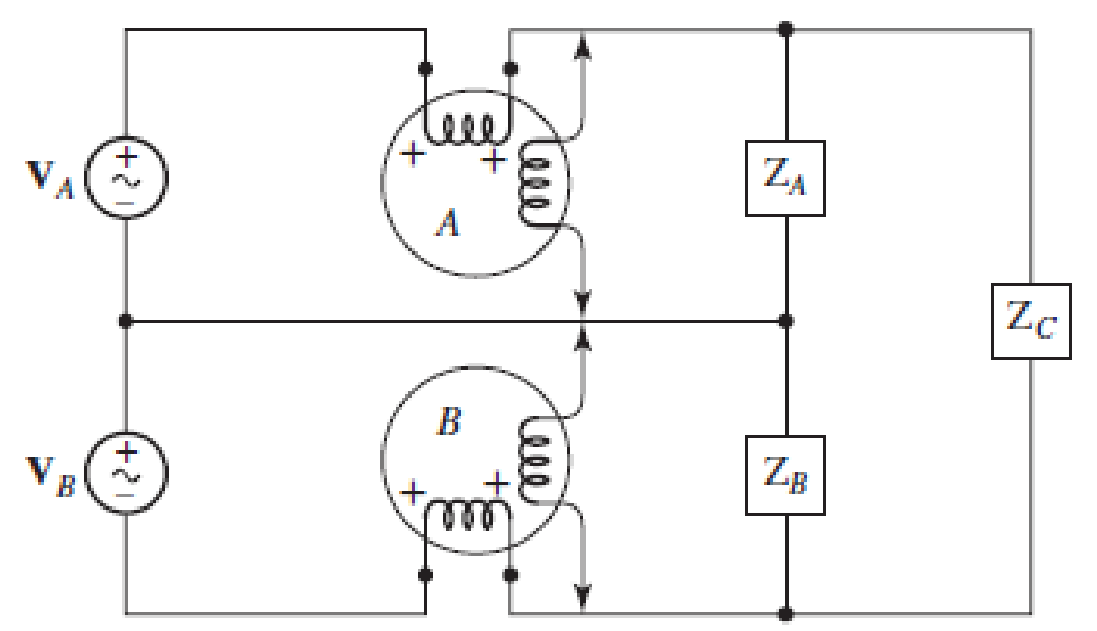
■ FIGURE 12.39
a.
Find the wattmeter readings in the circuit of Figure 12.39.
Answer to Problem 39E
The reading of wattmeter
Explanation of Solution
Given data:
The load impedance are
Calculation:
The given figure with mesh currents is shown in Figure 1.
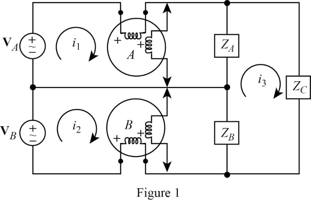
Apply Kirchhoff’s voltage law to the loop with current
Apply Kirchhoff’s voltage law to the loop with current
Apply Kirchhoff’s voltage law to the loop with current
Rearrange equation (1).
Substitute equation (4) in (3).
Simplify the equation as follows.
Substitute equation (5) in (4).
Substitute equation (6) in (2).
Simplify the equation as follows.
Substitute
Substitute
Calculate the power delivered by phase A as follows.
Calculate the power delivered by phase B as follows.
Conclusion:
Thus, the reading of wattmeter
b.
Verify that the sum of the wattmeter reading is equal to the total power taken by the three loads using LTspice.
Explanation of Solution
Formula used:
Write the expression for inductive reactance.
Here,
Write the expression for capacitive reactance.
Here,
Calculation:
Let us assume that the angular frequency
Substitute
Substitute
Substitute
LTspice Simulation:
Draw the given figure in LTspice as shown in Figure 2. V1 zero and V2 zero connected in the circuit to find the current flows through it.
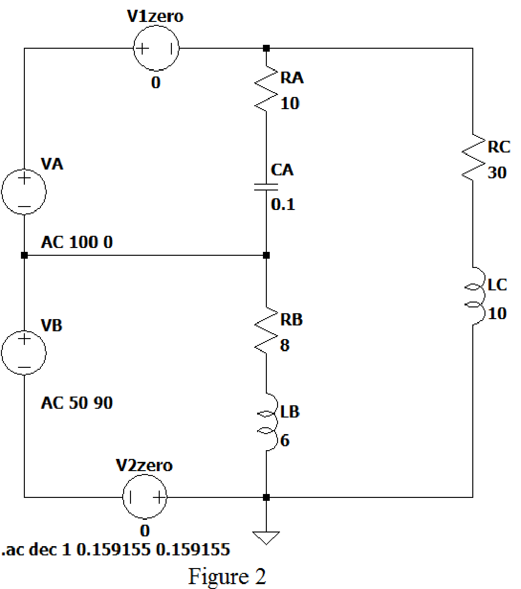
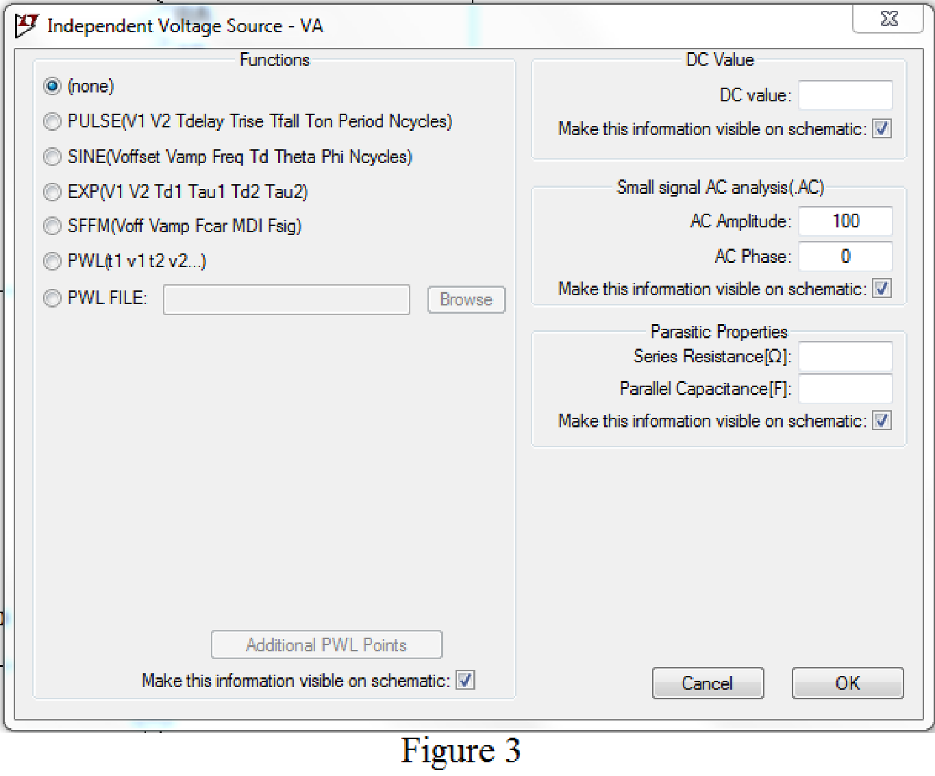
Set the values of voltages VA by right clicking on the voltage component, select none in “Functions” and enter the Small signal AC analysis parameters: AC amplitude as 100 for V1 as shown in Figure 3 for VA.
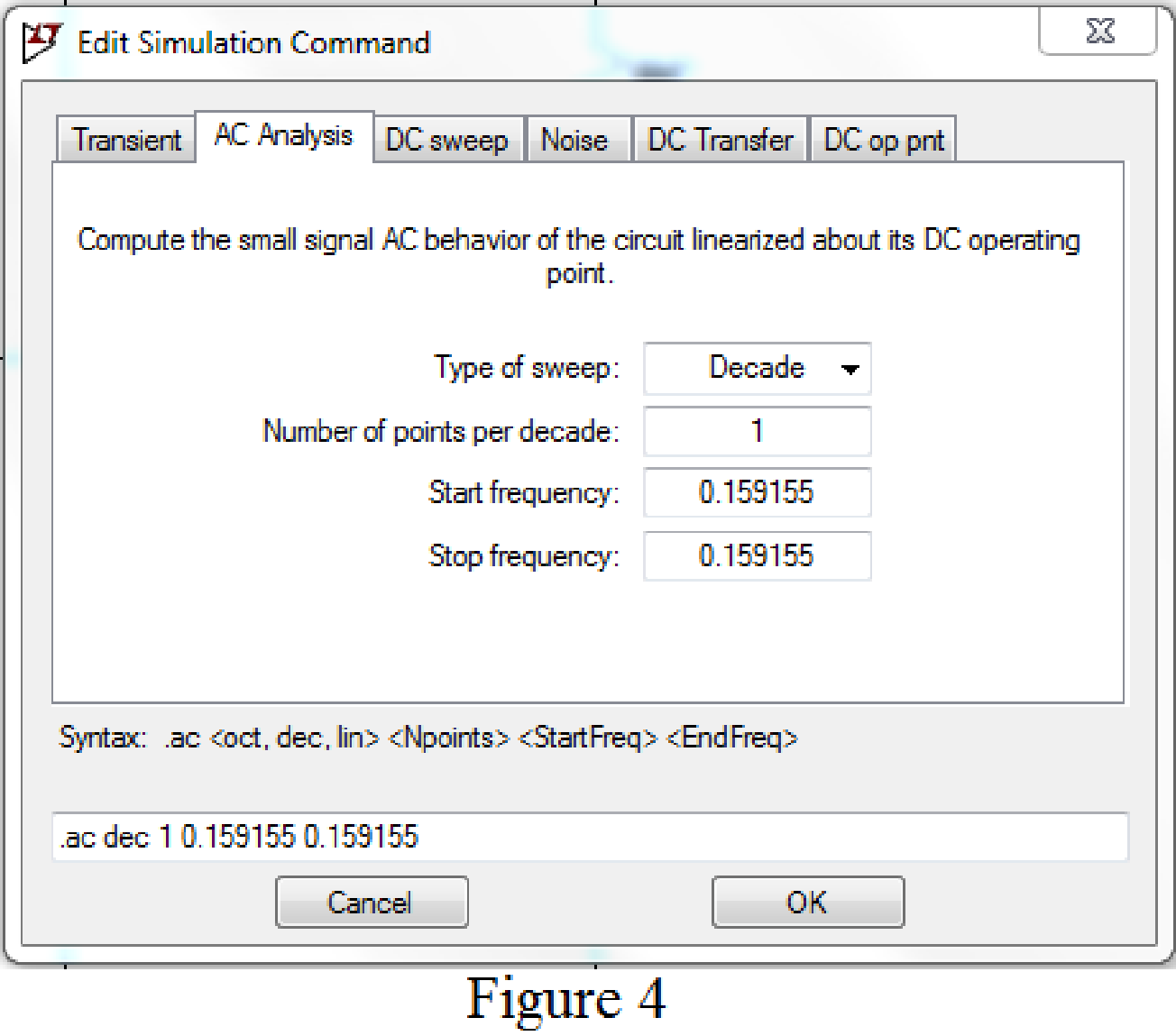
Now save the circuit, and open the “Edit Simulation command” choose AC analysis and select the sweep type as Decade, Number of points per decade 1, Start frequency and Stop frequency as 0.159155 Hz.
Now, run the simulation for the designed circuit. The output for the AC analysis will displays as shown in Figure 5.
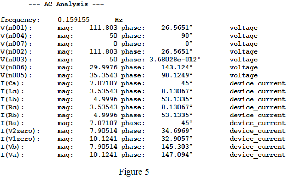
From above simulation results, the current flows through the load resistance are given below.
Calculate the power delivered to load
Calculate the power delivered to load
Calculate the power delivered to load
The total power delivered to the load is
The sum of the wattmeter reading is
Conclusion:
Thus, it is verified that sum of the wattmeter reading is equal to the total power taken by the three loads using LTspice.
Want to see more full solutions like this?
Chapter 12 Solutions
Loose Leaf for Engineering Circuit Analysis Format: Loose-leaf


- A three-phase, Y-connected synchronous generater supplies current of 10 A having phase angle of 20º lagging at 400 V. Find the load angle if Xs = 10 ohms per phase. Assume Rs to be negligible. Also, calculate the total generated real and reactive power.arrow_forwardA 3-phase, 50 Hz, overhead transmission line delivers 10 MW at 0·8 p.f. lagging and at 66 kV. The resistance and inductive reactance of the line per phase are 10 Ω and 20 Ω respectively while capacitance admittance is 4 × 10− 4 siemen. Calculate : (i) the sending end current (ii) sending end voltage (line-to-line) (iii) Power angle and sending end pf (iv) transmission efficiency Use nominal T methodarrow_forwardThe time-domain expressions for three line-to-neutral voltages at the terminals of a Y-connected load are v AN = 169.71 cos (ωt+ 26 ∘ ) V, v BN = 169.71 cos (ωt− 94 ∘ ) V, v CN = 169.71 cos (ωt− 94 ∘ ) V, What are the time-domain expressions for the three line-to-line voltages vAB, vBC, and vCA?arrow_forward
- A 530 kV, three phase transmission line with a 350 km length. The series impedance Z =(0.11+j0.72) Ω/ph/km and shunt admittance y = (j73 x e(-7)) S/ph/km. Evaluate the equivalent π-model and T-model parameters.arrow_forwardFind the characteristics of the load at the sending end and the efficiency of a three phase transmission line 160 km long delivering 15 MVA load at 110 kv, 50 Hz and 0.9 power factor (lagging) having inductance 1.356 mH/km per phase, capacitance 0.0085 uF/km per phase and resistance 40 ohms. Use nominal T-method Ans. Is = 70.3 20,8° Amp, Vsa.LD= 117.6 29.2 kV, power factor = 0.9898, n = 95.3%arrow_forwardA 3-phase overhead transmission line has the following constants :Resistance/phase = 10 ΩInductive reactance/phase = 35 ΩCapacitive admittance/phase = 3 × 10− 4 siemenIf the line supplied a balanced load of 40,000 kVA at 110 kV and 0·8 p.f. lagging, calculate :(i) sending end power factor (ii) percentage regulation(iii) transmission efficiencyarrow_forward
- A 3-phase, 50 Hz, overhead transmission line delivers 10 MW at 0·8 p.f. lagging and at 66 The resistance and inductive reactance of the line per phase are 10 W and 20 W respectively while capacitance admittance is 4 × 10- 4 siemen. Calculate : (i)the sending end current (ii) sending end voltage (line-to-line) (iii) sending end power factor (iv) transmission efficiency Use nominal T method.arrow_forwardA three-phase system includes a 346.4 V line-to-line supplying a three-phase motor rated 15KVA 0.8pf lag plus additional balanced constant impedance loads. The single-phase representation of the system is shown below. Assume that sources and loads are Y-connected. 1. What is the RMS value of the line current, I in A? 2. If this set of loads will be supplied through a service transformer. What should the minimum size of the transformer in kVA? 3. What should be the size of three-phase capacitor(that will be added to the load mix) to improve power factor to almost 0.95 lag?arrow_forwardq22/ A single phase, 50 Hz, overhead transmission line supplies 1300 kW at 26 kV, 0.65 p.f. lagging. The total resistance and line inductive reactance of the line are 4.75 Ω and 7.75 Ω respectively. Calculate the sending end voltage, voltage regulation, sending end power factor and efficiency of transmissionarrow_forward
- Design a power factor correction circuit with the value of parallel capacitance needed tocorrect a load of 179 kVAR at 0.85 lagging pf to unity pf. Assume that the load issupplied by a 110-V (rms), 60-Hz line.arrow_forwardAn alternating single phase circuit describes the instantaneous values of the applied voltage and the corresponding current as: v = 360 sin (201,69 t + π/6) and i = 36 sin (201,69 t - π/9) Calculate: the impedance, resistance and reactance of the circuit, the r.m.s.-values of the voltage and current, the true-, apparent- and reactive power in the circuit The time taken to reach -190 V for the second time. Sketch the phasor diagram of this circuitarrow_forwardA 50 Hz, 250 V single phase power line has the following loads placed across it in parallel; 4 kW ata pf of 0. 8 lagging; 6 kVA at a pf of 0.6 lagging; 5 kVA which includes 1.2 kVAR leading. Determinethe overall pf of the system and the capacitance of the capacitor which, if connected across themains restore the power factor to unity.arrow_forward
 Introductory Circuit Analysis (13th Edition)Electrical EngineeringISBN:9780133923605Author:Robert L. BoylestadPublisher:PEARSON
 Delmar's Standard Textbook Of ElectricityElectrical EngineeringISBN:9781337900348Author:Stephen L. HermanPublisher:Cengage Learning
 Programmable Logic ControllersElectrical EngineeringISBN:9780073373843Author:Frank D. PetruzellaPublisher:McGraw-Hill Education
 Fundamentals of Electric CircuitsElectrical EngineeringISBN:9780078028229Author:Charles K Alexander, Matthew SadikuPublisher:McGraw-Hill Education
 Electric Circuits. (11th Edition)Electrical EngineeringISBN:9780134746968Author:James W. Nilsson, Susan RiedelPublisher:PEARSON
 Engineering ElectromagneticsElectrical EngineeringISBN:9780078028151Author:Hayt, William H. (william Hart), Jr, BUCK, John A.Publisher:Mcgraw-hill Education,