
Concept explainers
Videos
Repeat Exercise 17 with Rw = 10 Ω, and verify your answers with an appropriate set of simulations if the operating frequency is 60 Hz.
Assume the system shown in Fig. 12.34 is balanced, Rw = 0, Van = 208∠0° V, and a positive phase sequence applies. Calculate all phase and line currents, and all phase and line voltages, if Zp is equal to (a) 1 kΩ; (b) 100 + j48 Ω; (c) 100 − j48 Ω.
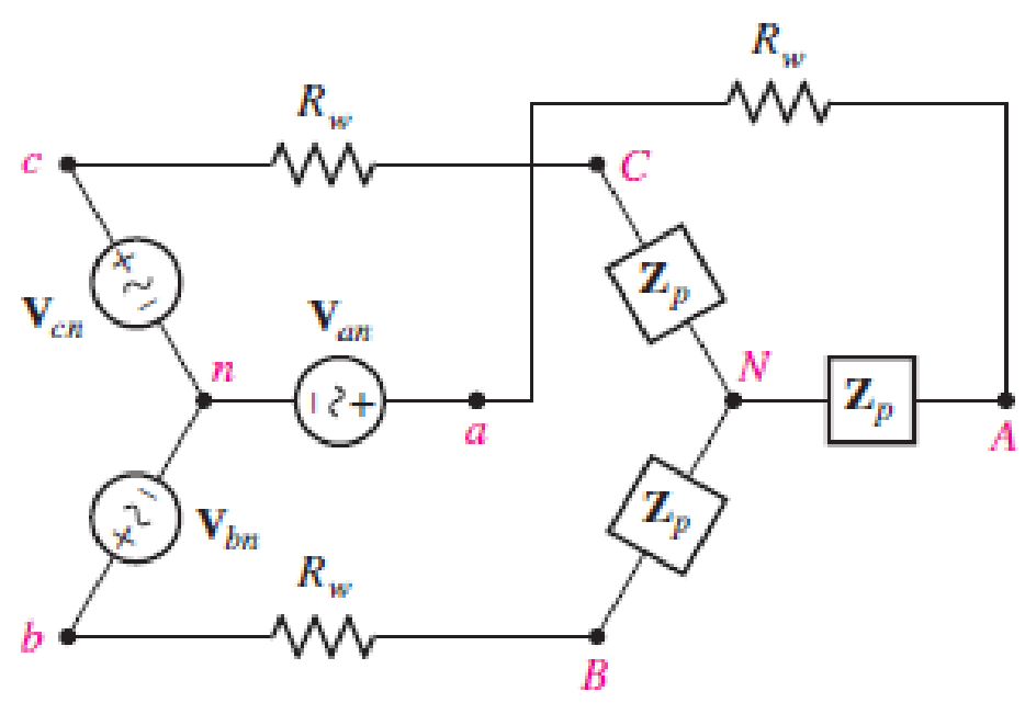
■ FIGURE 12.34
(a)
Find the line and phase currents, line and phase voltages at the load when the load impedance
Answer to Problem 18E
The line and phase currents are
Explanation of Solution
Given data:
The line resistance
The load impedance
The source phase voltage is
The simulation operation frequency is
LTspice Simulation:
Draw the given circuit diagram as shown in Figure 1, where 1, 2, and 3 are placed for node representations using Label Net.
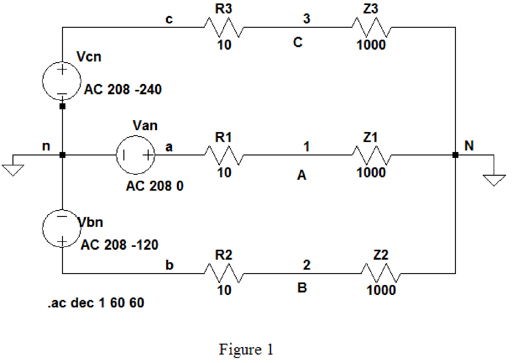
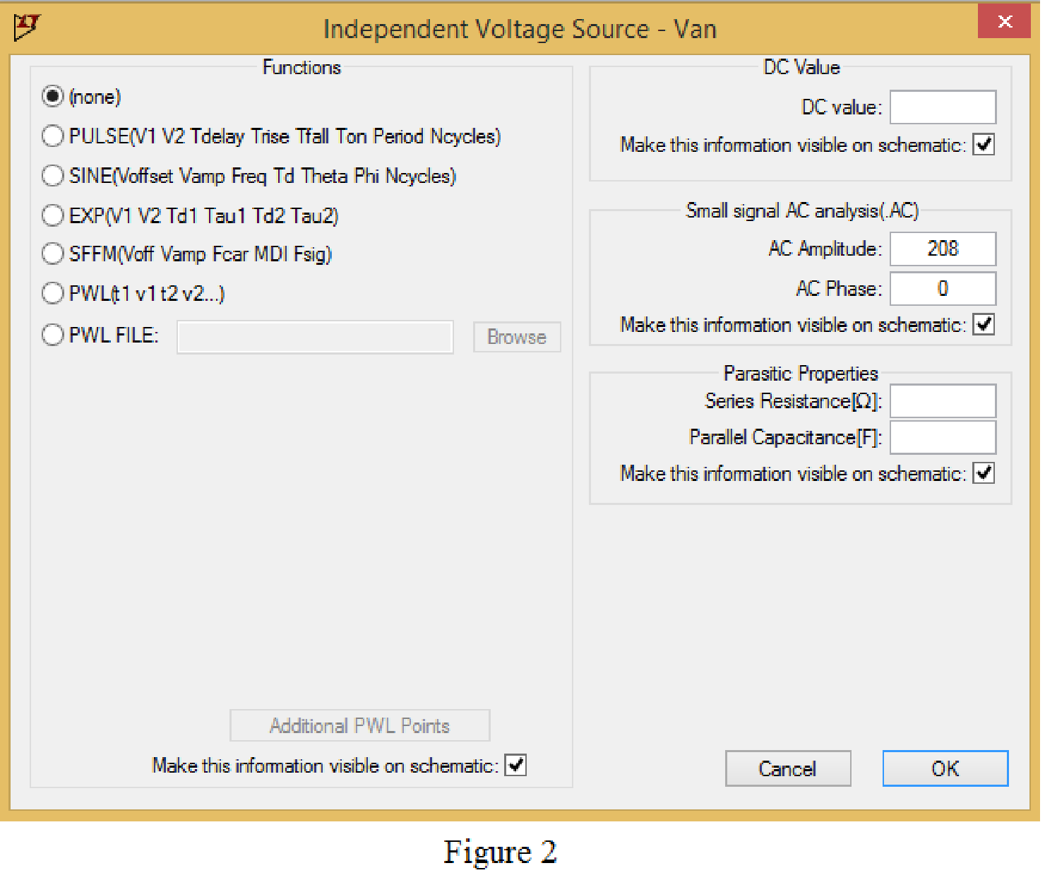
Set the values of voltages Van, Vbn and Vcn by right clicking on the voltage component, select none in “Functions” and enter the Small signal AC analysis parameters: AC amplitude as 208 and AC phase as 0 for V1, and enter other two voltage values accordingly positive phase sequence as shown in Figure 2 for V1.
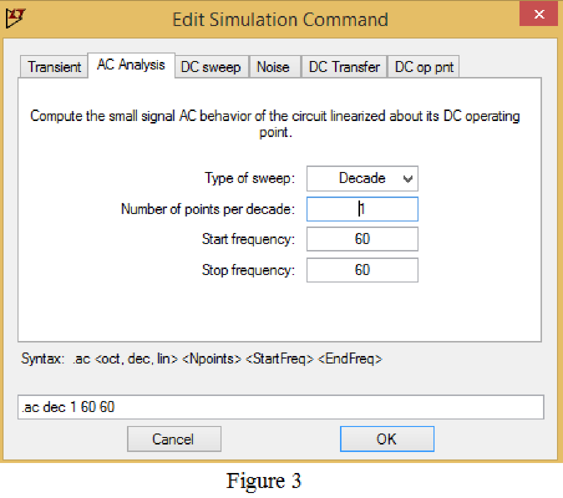
Now save the circuit, and open the “Edit Simulation command” choose AC analysis and select the sweep type as Decade, Number of points per decade 1, Start frequency and Stop frequency as 60 Hz shown in Figure 3.
Now, run the simulation for the designed circuit. The output for the AC analysis will displays as shown in Figure 4.
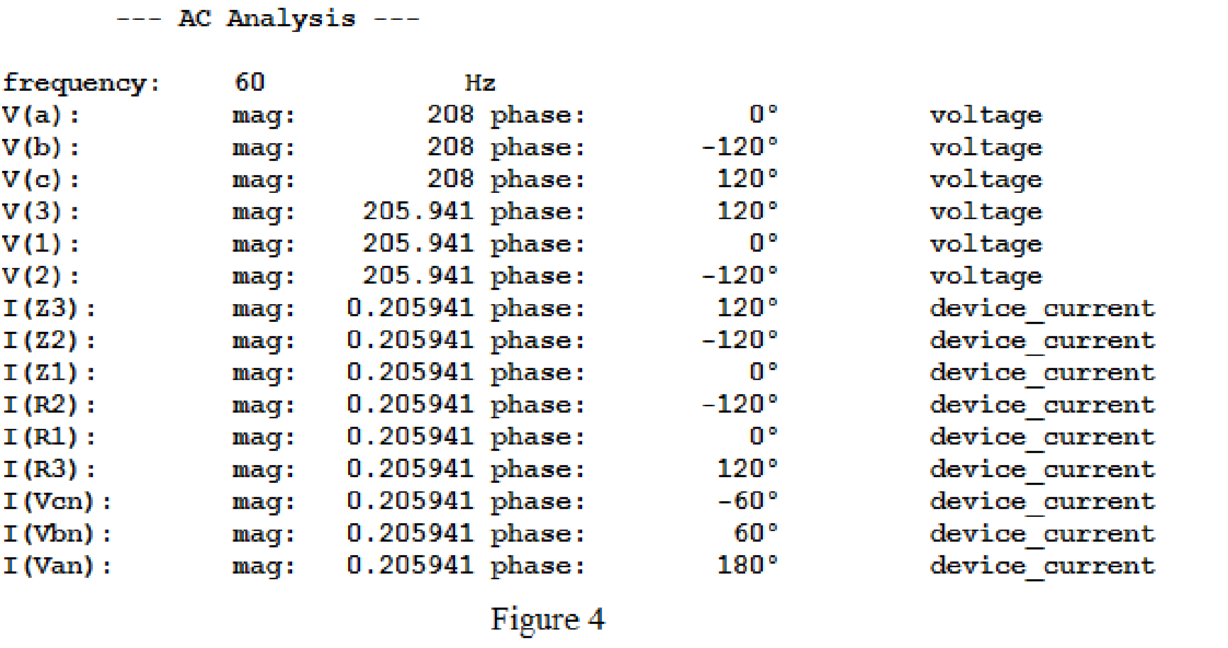
For the wye-wye connection, phase currents and line currents are equal and they are equals to
Then,
In above simulation results, the phase voltages at the load
Then, the phase voltages at the load are,
The magnitude of the phase voltages is
Write the formula to find the line voltage
Substitute
Write the formula to find the line voltage
Substitute
Write the formula to find the line voltage
Substitute
Conclusion:
Thus, the line and phase currents are
(b)
Find the line and phase currents, line and phase voltages at the load when the load impedance
Answer to Problem 18E
The line and phase currents are
The phase voltages are
Explanation of Solution
Given data:
Refer to part (a).
LTspice Simulation:
The load impedance is given as,
Where load resistance is
Write the formula to find the inductive reactance as follows.
Substitute
Draw the given circuit diagram as shown in Figure 5 for the load impedance
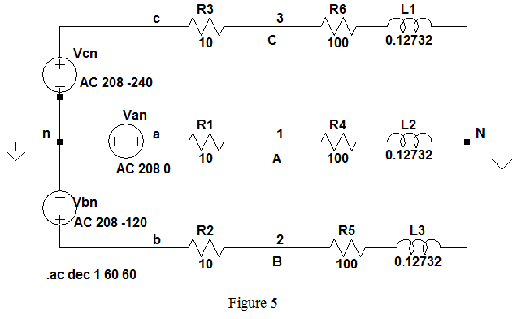
Keep the same simulation settings as given in Part(a) and run the simulation, then the output for the AC analysis will displays as shown in Figure 6.
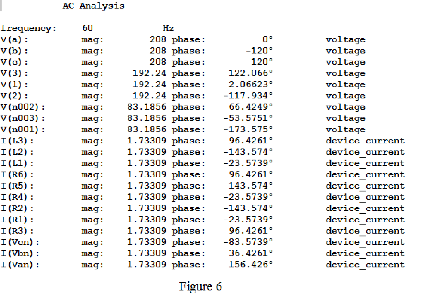
From above simulation results I(R1) or I(R4) or I(L1) is equals to
Then,
The phase voltages at the load
Then, the phase voltages at the load are,
The magnitude of the phase voltages is
Write the formula to find the line voltage
Substitute
Write the formula to find the line voltage
Substitute
Write the formula to find the line voltage
Substitute
Conclusion:
Thus, the line and phase currents are
The phase voltages are
(c)
Find the line and phase currents, line and phase voltages at the load when the load impedance
Answer to Problem 18E
The line and phase currents are
The phase voltages are
Explanation of Solution
Given data:
Refer to part (a).
LTspice Simulation:
The load impedance is given as,
Where load resistance is
Write the formula to find the inductive reactance as follows.
Substitute
Draw the given circuit diagram as shown in Figure 5 for the load impedance
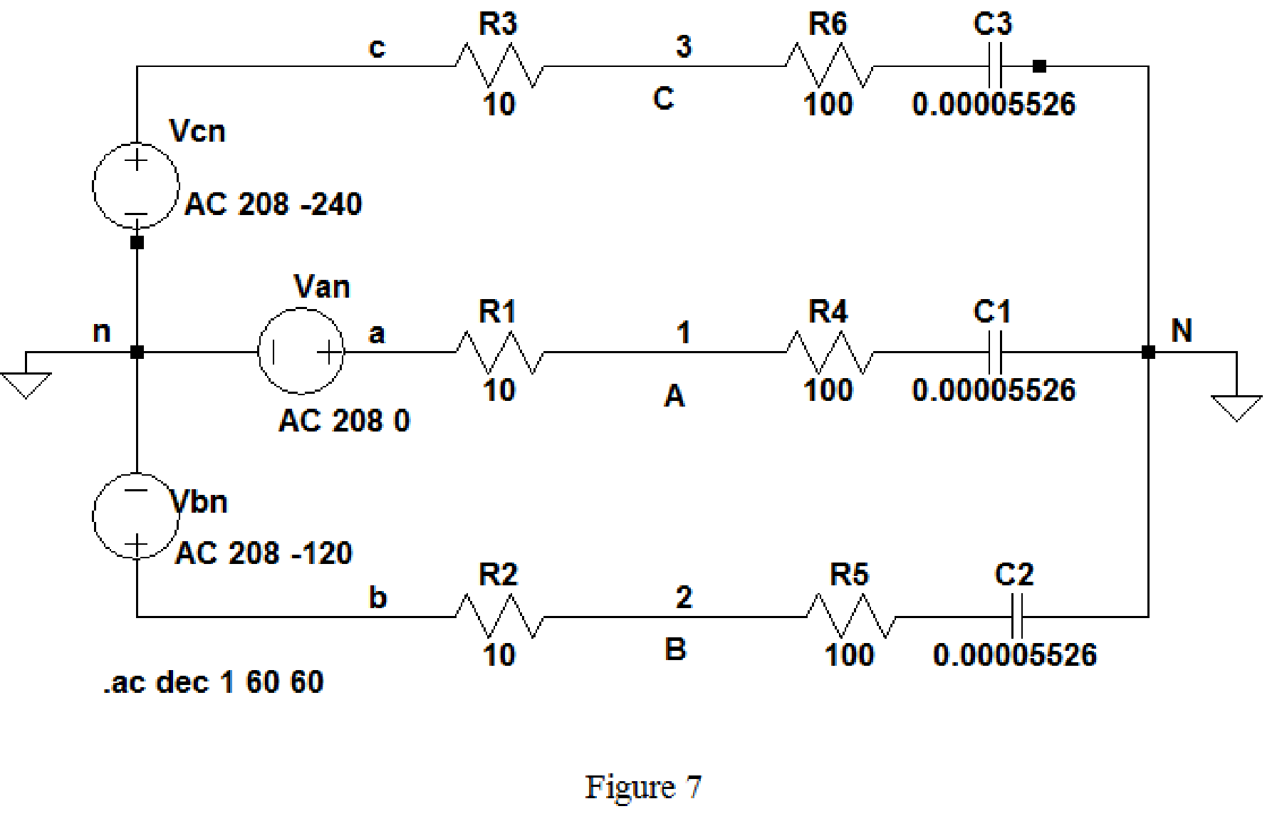
Keep the same simulation settings as given in part(a) and run the simulation, then the output for the AC analysis will displays as shown in Figure 8.
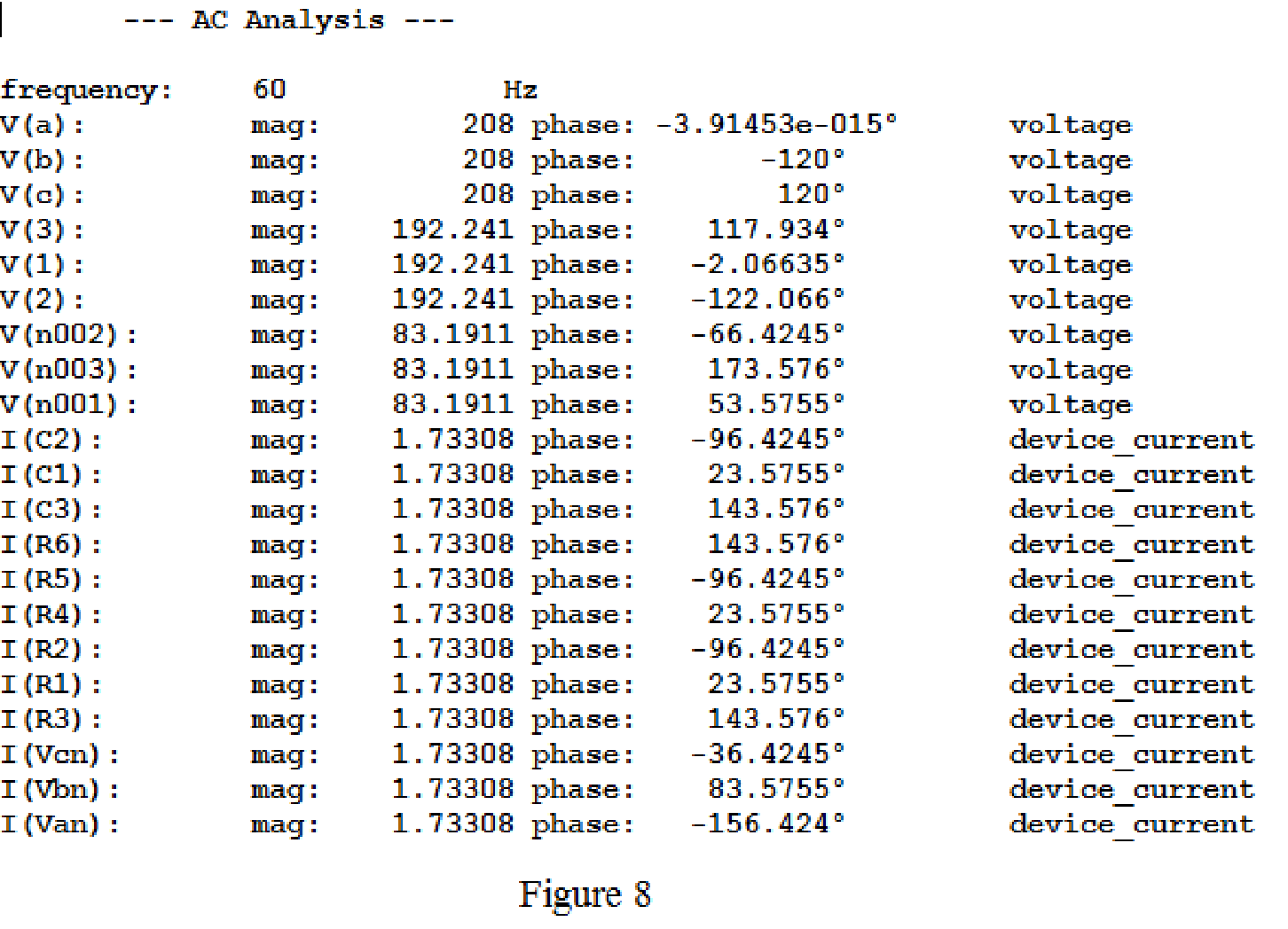
From above simulation results, since the phase currents and line currents are equal, I(R1) or I(R4) or I(C1) is equals to
Then,
The phase voltages at the load
Then, the phase voltages at the load are,
Use the same formula given in equation (1) to find the line voltage
Use the same formula given in equation (2) to find the line voltage
Use the same formula given in equation (3) to find the line voltage
Conclusion:
Thus, the line and phase currents are
The phase voltages are
Want to see more full solutions like this?
Chapter 12 Solutions
Loose Leaf for Engineering Circuit Analysis Format: Loose-leaf


- A three-phase system includes a 346.4 V line-to-line supplying a three-phase motor rated 15KVA 0.8pf lag plus additional balanced constant impedance loads. The single-phase representation of the system is shown below. Assume that sources and loads are Y-connected. 1. What is the RMS value of the line current, I in A? 2. If this set of loads will be supplied through a service transformer. What should the minimum size of the transformer in kVA? 3. What should be the size of three-phase capacitor(that will be added to the load mix) to improve power factor to almost 0.95 lag?arrow_forwardA three-phase, Y-connected synchronous generater supplies current of 10 A having phase angle of 20º lagging at 400 V. Find the load angle if Xs = 10 ohms per phase. Assume Rs to be negligible. Also, calculate the total generated real and reactive power.arrow_forwardA short 230 kV transmission line with a reactance of 18 ph supplies a load at 0.85 pf. lag. For a line current of 1000 A, the receiving and sending end voltages are to be maintained at 230 kV. Calculate: (i) rating of synchronous capacitor required (ii) load current (iii) load MVA. Neglect power drawn by capacitor.arrow_forward
- A single – phase transmission line supplies a reactive load at a lagging power factor. The load draws 1.2 pu current at 0.6 pu voltage while drawing 0.5 pu (true) power. If the base voltage is 20 kV and the base current is 160 A, calculate the power factor and the ohmic value of the resistance of the load.arrow_forwardA single phase distributor 2 kilometers long supplies a load of 120 A at 0·8 p.f. lagging at its far end and a load of 80 A at 0·9 p.f. lagging at its mid-point. Both power factors are referred to the voltage at the far end. The resistance and reactance per km (go and return) are 0·05 Ω and 0·1 Ω respectively. If the voltage at the far end is maintained at 230 V, calculate : • voltage at the sending end • phase angle between voltages at the two ends.arrow_forwardA Δ-connected, 60−Hz, balanced, 3ϕ, positive-sequence voltage source is connected to a Δ-connected, symmetric 3ϕ load via a non-ideal transmission line. The line-line voltage magnitude of the source is 480VRMS. The series impedance of each phase of the transmission line is 0.1+j1.5Ω. The impedance of each leg of the load is 3+j6Ω. a. What is the total, 3ϕ complex power consumed by the load. b. What are the total active power losses (all three phases) in the transmission line?arrow_forward
- A 3-phase, 50 Hz, 20 km long overhead line supplies 1000 kW at 11kV, 0.8 p.f. lagging. The line resistance is 0.03 & per phase per km and line inductance is 0.7 mH per phase per km. Calculate the sending end voltage, voltage regulation and efficiency of transmission.arrow_forwardFind the characteristics of the load at the sending end and the efficiency of a three phase transmission line 160 km long delivering 15 MVA load at 110 kv, 50 Hz and 0.9 power factor (lagging) having inductance 1.356 mH/km per phase, capacitance 0.0085 uF/km per phase and resistance 40 ohms. Use nominal T-method Ans. Is = 70.3 20,8° Amp, Vsa.LD= 117.6 29.2 kV, power factor = 0.9898, n = 95.3%arrow_forwardA 3-phase Y-connected source (400V) supplies a 3-phase Y-connected load (3xZload = 27 + 9.0 ohm) via a non-ideal, three-core cable. No neutral line is available. Each conductor of the cable has an impedance Zcable = 80 + 2.1 mOhm a. Measure the phase shift angle between line voltage and phase voltage. b. Because of a fault, one of the three load impedances changes to half its original value. What happens to the phase voltages at the load.arrow_forward
- A transmission line of impedance (0.05 + j0.02) pu interconnects the buses of a switchyard and a bulk supply point. The receiving end apparent power is (1.0 + j0.6) pu and sending end voltage, 1/0°pu. Estimate the following: i) Receiving end voltage after two iterations ii) Perform two further iterations to test the convergence of the value of receiving end voltage deduced in (i) iii) load currentarrow_forwardExercise 1: A three-phase 3Φ transmission line has an impedance of 0.62+j35.06Ω/phase and supplies a three-phase load of 100MW with a power factor (fp) of 0.8 lagging at 200kV. Taking 100MVA and 215kV as a base, we ask: a-) Calculate the impedance of the line in p.u;b-) Calculate the current consumed by the load in p.u;c-) Calculate the load voltage in p.u; PLEASE, TYPE, HAND WRITING GETS UNDERSTANDING.arrow_forwardThe length of a three-phase power transmission line with a nominal operating voltage of 69 kV is 16km. The impedance of the transmission line per unit length is 0.125 + j0.4375 ohm/ km. At the end of the line, a 70 MVA star connected load with a power factor of 0.8 back under 69 kV interphase voltage is fed. Capacitive circuit element with a capacitance of 19.14 mikro F / phase is placed as shunt at the end of the transmission line. According to these given; a) Line head voltage and current, b) Calculate the active and reactive power per line.arrow_forward
 Introductory Circuit Analysis (13th Edition)Electrical EngineeringISBN:9780133923605Author:Robert L. BoylestadPublisher:PEARSON
 Delmar's Standard Textbook Of ElectricityElectrical EngineeringISBN:9781337900348Author:Stephen L. HermanPublisher:Cengage Learning
 Programmable Logic ControllersElectrical EngineeringISBN:9780073373843Author:Frank D. PetruzellaPublisher:McGraw-Hill Education
 Fundamentals of Electric CircuitsElectrical EngineeringISBN:9780078028229Author:Charles K Alexander, Matthew SadikuPublisher:McGraw-Hill Education
 Electric Circuits. (11th Edition)Electrical EngineeringISBN:9780134746968Author:James W. Nilsson, Susan RiedelPublisher:PEARSON
 Engineering ElectromagneticsElectrical EngineeringISBN:9780078028151Author:Hayt, William H. (william Hart), Jr, BUCK, John A.Publisher:Mcgraw-hill Education,