
Concept explainers
Videos
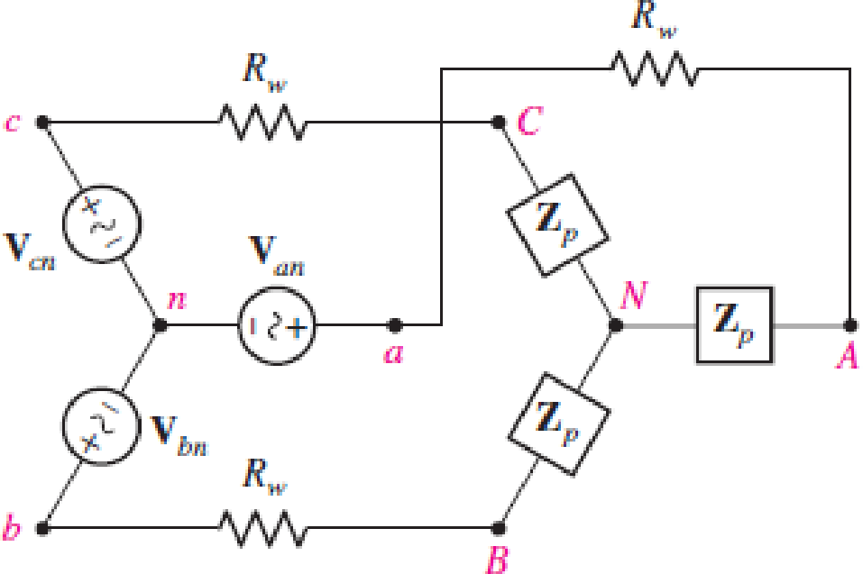
Assume the system shown in Fig. 12.34 is balanced, Rw = 0,  , and a positive phase sequence applies. Calculate all phase and line currents, and all phase and line voltages, if Zp is equal to (a) 1 kΩ; (b) 100 + j48 Ω; (c) 100 − j48 Ω.
(a)
All the line and phase currents and all the line and phase voltages for the given load impedance.
Answer to Problem 17E
The line and phase currents in sequence are
Explanation of Solution
Given data:
The resistance of the wire
The phase to neutral voltage
The load impedance
Calculation:
The system follows positive sequence hence the phase to neutral voltages will be,
For phase
For phase
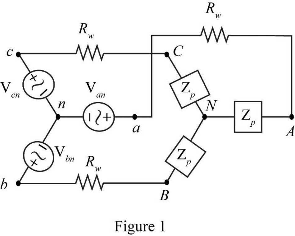
The required diagram is shown in Figure 1.
The line voltage between phase
Substitute
The system follows positive sequence hence the line to line voltages will be,
All the phase and line voltages are independent of the impedance value and hence these values will remain same for all the values of load impedance
The conversion from
Hence, the load impedance
Since the given system is a star connected system, the phase currents will be equal to the line currents.
The phase
Here,
The phase
Substitute
The phase
Here,
The phase
Substitute
The phase
Here,
The phase
Substitute
Conclusion:
Therefore, the line and phase currents in sequence are
(b)
All the line and phase currents and all the line and phase voltages for the given load impedance.
Answer to Problem 17E
The line and phase currents in sequence are
Explanation of Solution
Given data:
The load impedance
Calculation:
All the phase and line voltages are independent of the impedance value and hence these values will remain same for all the values of load impedance
The phase
Here,
The phase
Substitute
The phase
Here,
The phase
Substitute
The phase
Here,
The phase
Substitute
Conclusion:
Therefore, the line and phase currents in sequence are
(c)
All the line and phase currents and all the line and phase voltages for the given load impedance.
Answer to Problem 17E
The line and phase currents in sequence are
Explanation of Solution
Given data:
The load impedance
Calculation:
All the phase and line voltages are independent of the impedance value and hence these values will remain same for all the values of load impedance
The phase
Here,
The phase
Substitute
The phase
Here,
The phase
Substitute
The phase
Here,
The phase
Substitute
Conclusion:
Therefore, the line and phase currents in sequence are
Want to see more full solutions like this?
Chapter 12 Solutions
Loose Leaf for Engineering Circuit Analysis Format: Loose-leaf


- The phase voltage at the terminals of a balanced three-phase Yconnected load is 2400 V. The load has an impedance of 16 + j12 Ω/ϕ and is fed from a line having an impedance of 0.10 + j0.80 Ω/ϕ. The Yconnected source at the sending end of the line has a phase sequence of acb and an internal impedance of 0.02 + j0.16 Ω/ϕ. Use the a-phase voltage at the load as the reference and calculate (a) the line currents IaA, IbB, and IcC; (b) the line voltages at the source, Vab, Vbc, and Vca; and (c) the internal phase-to-neutral voltages at the source, Va ′n, Vb′n, and Vc′n.arrow_forwardA 12470 Vrms, 3-phase 60 Hz supply is applied to a balanced Delta-connected 3-phase load consisting of 3 identical impedances of Z=48∠ 36.87°Ω Calculate (a) The current in each line.arrow_forwardA load connected in delta, with impedances of 24 ≮ 20°, has a current IAC = 20 ≮ 10°, Calculate:a- Phase currentsb- Line currentsc- Line-Line voltagesarrow_forward
- 2. A 12500 kVA load is supplied at a power factor of 0·8 lagging by a 3-phase transmission line whosevoltage is to be maintained at 33 kV at both ends. Determine the capacity of the synchronous condenserto be installed at the receiving end. The impedance of the line is (4 + j 12) ohms per phase. solution is [11490 kVAR]arrow_forwardPROBLEM 1. A three-phase transmission line is 100 km long. Its parameters are: z= (0.08 + j0.45) Ω/km y=j5 μS/km At the generating end it has a voltage of 115 kV L-L, and it is delivering a real power of PS= 51 MW and a reactive power of QS=31.6 MVARS. a. Find the parameters A,B,C and D. b. Determine the voltage and current at the receiving end. C. Calculate the regulation of the load node.arrow_forwardA three-phase line with an impedance of (0.2+j1.0)/ phase feeds three balanced three-phase loads connected in parallel. Load 1: Absorbs a total of 150 kW and 120 kvar. Load 2: Delta connected with an impedance of (150j48)/phase. Load 3: 120 kVA at 0.6 PF leading. If the line-to-neutral voltage at the load end of the line is 2000 v (rms), determine the magnitude of the line-to-line voltage at the source end of the line.arrow_forward
- A Y-Y three-phase system has a source of 380 V and a load of impedance of 6+j5 Ohm/phase through a transmission line of 2+j 1 Ohm/phase.Plot this Y-Y three-phase system then calculate complex power supplied by the source.arrow_forwardA balanced delta-connected lood with impedance per phase of 30<30 ohms is connected to an abc-sequence balanced three-phase source with eAC = -120√2 cos (120πt + π/6) V through conductors with negligible impedances. Determine the line currents, load phase currents and the total complex power drawn by the lood. Write your values in polar form.arrow_forwardThe following three-phase loads are connected to a short transmission line with impedance per wire of 4 + j7 ohms: Load 1: Resistive load drawing 80 A, Load 2: Capacitor drawing 60 A, Load 3: Inductive load drawing 50 A at 80 % power factor. What is the sending end power factor for a receiving end voltage of 34.5 kV? a. 96 % b. 97 % c. 98 % d. 99 %arrow_forward
- Exercise 1: A three-phase 3Φ transmission line has an impedance of 0.62+j35.06Ω/phase and supplies a three-phase load of 100MW with a power factor (fp) of 0.8 lagging at 200kV. Taking 100MVA and 215kV as a base, we ask: a-) Calculate the impedance of the line in p.u;b-) Calculate the current consumed by the load in p.u;c-) Calculate the load voltage in p.u; PLEASE, TYPE, HAND WRITING GETS UNDERSTANDING.arrow_forwardA three phase delta-connected load of 15+j18 per phase is supplied by an abc-sequence balance three phase wye connected source with a line voltage of 400v. The line impedance is 1+j2 per phase. Taking EA as a refeference, determine the line currents, phase load currents, phase voltages, and total complex power supplied by the source.arrow_forwardA 370 kV, three phase transmission line with a 410 km length. The series impedance Z =(0.45+j0.94) Ω/ph/km and shunt admittance y = (j57 x e(-7)) S/ph/km. Evaluate the equivalent π-model and T-model parameters.arrow_forward
 Power System Analysis and Design (MindTap Course ...Electrical EngineeringISBN:9781305632134Author:J. Duncan Glover, Thomas Overbye, Mulukutla S. SarmaPublisher:Cengage Learning