
Videos
For the inductive element of Fig. 15.83:
a. Write the current in phasor form.
b. Calculate the voltage across the inductor in phasor form.
c. Sketch the phasor diagram of the voltage and current.
d. Write the voltage in the sinusoidal format.
e. Sketch the waveform of the voltage and current.
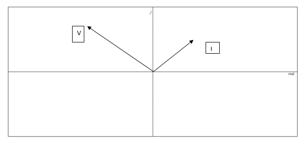
Fig. 15.83
Want to see the full answer?
Check out a sample textbook solution
Chapter 15 Solutions
Laboratory Manual for Introductory Circuit Analysis
Additional Engineering Textbook Solutions
Programmable Logic Controllers
Electric Circuits. (11th Edition)
Electric Circuits (10th Edition)
Principles and Applications of Electrical Engineering
ANALYSIS+DESIGN OF LINEAR CIRCUITS(LL)
Microelectronics: Circuit Analysis and Design


- Consider the following sinusoidal plot of the instantaneous voltage of an inductor as a function of time.What is its root-mean-square voltage?arrow_forward16. Determine the following from the given R-L-C series circuit: i) Impedance Z ii) Current i iii) Voltage across resistance V iv) Voltage across inductance V₁ v) Voltage across capacitance Ve vi) Total power delivered vii) Power factor 70.7 sheet Ⓒ 40 R = 30 X₁70 X 30 www vooarrow_forwardFind the equivalent inductive reactance if the frequency is 61 Hz. ... a m IH L, C 6 H L, 3 6 H L,R 4 H 2 H зн Round your answer to 2 decimal places.arrow_forward
- Draw the phasor diagram. Find magnitudes and positions of all the quantities. Please show complete solution and round off answers up to the 3rd decimal place. Thank you!arrow_forwardWhen a resistor is connected across the terminals of an ac generator (117 V) that has a fixed frequency, there is a current of 0.332 A in the resistor. When an inductor is connected across the terminals of the same generator, there is a current of 0.365 A in the inductor. When both the resistor and the inductor are connected in series between the terminals of this generator, what is (a) the impedance of the series combination and (b) the phase angle between the current and the voltage of the generator? Note: The ac current and voltage are rms values and power is an average value unless indicated otherwise. (a) Number (b) Number Buda i Vrms R Irms.R Circuit 1 Units Units Vrms. Irms, L Circuit 2 > L Vrms R www Circuit 3arrow_forwardThe explanation must be typed, the explanation must be in the simplest form/terms, if applicable ensure proper significant figures and use variable space.arrow_forward
- I) Convert the following phasors to the time domain if the frequency is I KHz. . h-3 A a) k- 12 /40 b)arrow_forwardPlease answer in typing format please yy Please all subpart is compulsory Please in typing formatarrow_forward:D A docs.google.com/forms/d/1 o المرحلة والشعبة: * A non-sinusoidal voltage (e=20+15sin1000t+ 10sin3000t+5sin4000t) Volt is applied to the circuit shown. Find the ?total power iT 42 İL -J92 J42 44.03 W 86.08 W 88.06 W 44.04 W n-sinusoidal wave can be طلب الإذن بالتعديل of sine waves with .harmonic frequencies IIarrow_forward
 Power System Analysis and Design (MindTap Course ...Electrical EngineeringISBN:9781305632134Author:J. Duncan Glover, Thomas Overbye, Mulukutla S. SarmaPublisher:Cengage Learning