
Laboratory Manual for Introductory Circuit Analysis
13th Edition
ISBN: 9780133923780
Author: Robert L. Boylestad, Gabriel Kousourou
Publisher: PEARSON
expand_more
expand_more
format_list_bulleted
Concept explainers
Videos
Textbook Question
Chapter 15, Problem 6P
For the capacitive element of Fig. 15.86:
- Write the voltage in phasor form.
- Calculate the current of the capacitor in phasor form.
- Sketch the phasor diagram of the voltage and current.
- Write the current in the sinusoidal format.
- Sketch the waveform of the voltage and current.
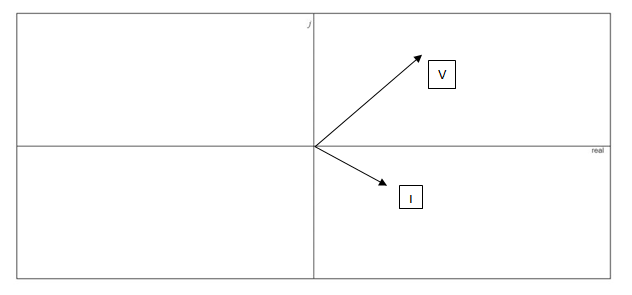
Fig. 15.86
Expert Solution & Answer
Want to see the full answer?
Check out a sample textbook solution
Students have asked these similar questions
a) Find the phasor current I.
Enter your answer using polar notation.
b) Find the power delivered by the source and the reactive power delivered by the source.
c) Find the apparent power delivered by the source and the power factor
What is the reactance of 3.00 microfarad capacitor? What is the impedance of the capacitor in series of 300 ohms?
58. Two capacitors, a 20 µF and a 30 µF, are connected in series to a 60-Hz source. What is the total capacitive
reactance?
a. 117.96 N
b. 221.04 N
c. 253.05 N
d. 333.16 N
Chapter 15 Solutions
Laboratory Manual for Introductory Circuit Analysis
Ch. 15 - For the resistive element in Fig. 15.81: Write the...Ch. 15 - For the resistive element in Fig. 15.82: Write the...Ch. 15 - For the inductive element of Fig. 15.83: a. Write...Ch. 15 - For the inductive element of Fig. 15.84: Calculate...Ch. 15 - For the inductive element of Fig. 15.85: Write the...Ch. 15 - For the capacitive element of Fig. 15.86: Write...Ch. 15 - For the capacitive element of Fig. 15.87:...Ch. 15 - For the capacitive element of Fig. 15.88: Write...Ch. 15 - Sketch the impedance diagram of a 120 k resistor.Ch. 15 - Sketch the impedance diagram of a 5 mH coil...
Ch. 15 - Sketch the impedance diagram of a 0.02 F capacitor...Ch. 15 - Calculate the total impedance of the circuits in...Ch. 15 - Calculate the total impedance of the circuits in...Ch. 15 - Find the type and impedance in ohms of the series...Ch. 15 - For the circuit in Fig. 15.92 Find the total...Ch. 15 - Repeat problem 15 for the circuit in Fig. 15.93,...Ch. 15 - For the circuit in Fig. 15.94: Find the total...Ch. 15 - Repeat Problem 17 for the circuit in Fig. 15.95...Ch. 15 - For the circuit of Fig. 15.96: Find the total...Ch. 15 - For the circuit of Fig. 15.97: Find the current...Ch. 15 - Prob. 21PCh. 15 - Using the oscilloscope reading in Fig. 15.99,...Ch. 15 - Using the DMM current reading and the oscilloscope...Ch. 15 - Using the oscilloscope reading in Fig. 15.101:...Ch. 15 - An electrical load has a power factor of 0.8...Ch. 15 - Find the series element or elements that must be...Ch. 15 - Calculate the voltages V1andV2 for the circuits in...Ch. 15 - Calculate the voltages V1andV2 for the circuits in...Ch. 15 - For the circuit in Fig. 15.105: Determine...Ch. 15 - For the circuit in Fig. 15.106: a. Plot ZT and T...Ch. 15 - Prob. 31PCh. 15 - For the series R-L-C circuit in Fig. 15.108: Plot...Ch. 15 - For the series R-C circuit in Fig. 15.109:...Ch. 15 - For the circuit in Fig. 15.110, determine the...Ch. 15 - For the oscilloscope traces in Fig. 15.111:...Ch. 15 - For the network in Fig. 15.92 (usef=1kHz):...Ch. 15 - For the network in Fig. 15.93: Plot the impedance...Ch. 15 - For the network in Fig. 15.105: Find the rms...
Additional Engineering Textbook Solutions
Find more solutions based on key concepts
With respect to the circuit in Fig. 5.90, (a) employ Thévenin’s theorem to determine the equivalent network see...
Loose Leaf for Engineering Circuit Analysis Format: Loose-leaf
What is the color code for a 365- five-band precision resistor with a tolerance of 5 percent?
ELECTRICITY FOR TRADES (LOOSELEAF)
Identify the type of input and output configuration for each diff-amp in Figure 18-35.
Electronics Fundamentals: Circuits, Devices & Applications
Design an ideal inverting op-amp circuit such that the voltage gain is Av=25 . The maximum current in any resis...
Microelectronics: Circuit Analysis and Design
Does the severity of an electric shock increase ordecrease with eh of the following changes? a. A decrease in t...
Electric Motors and Control Systems
The voltage source of the circuit shown in Fig. P1.29 is given by s(t)=25cos(4104t45)(V). Obtain an expression ...
Fundamentals of Applied Electromagnetics (7th Edition)
Knowledge Booster


Learn more about
Need a deep-dive on the concept behind this application? Look no further. Learn more about this topic, electrical-engineering and related others by exploring similar questions and additional content below.Similar questions
- A capacitor has a reactance of 80 ohms when connected to a 50 Hz supply. Calculate the value of capacitance.a. 39.79 microfaradb. 39.97 microfaradc. 93.79 microfaradd. 93.97 microfaradKindly provide a CLEAR and COMPLETE solution.arrow_forwardImpedance of AC circuit and Admittance of AC circuitSHOW THE CIRCUIT USING ANY SOFTWARE OR YOU CAN DRAW IT MANUAALYY thNAKSSarrow_forward13. When a capacitor is connected to an AC supply, the current A. Leads the voltage by pi/2 rad B. Leads the voltage by 180 degrees C. In phase with the voltage D. Lags the voltage by 90 degreesarrow_forward
- b. 16 x 10 sim 10r + 2) 13. Determine the capacitive reactance (in ohms) of a 0.2 μF capacitor for a. de and for the following frequencies: b. 60 Hz se rooctance is given. c. 2 kHz d. 2 MHzarrow_forwardDetermine the Inductance that has a Reactance of 2 KOhms, at a frequency of 14.47 KHz. show all the stepsarrow_forwardQUESTION 3 An inductor, a capacitor, and a resistor are connected in parallel with a function generator. The inductor draws 100mA RMS, the capacitor draws 150mA RMS, and the resistor draws 200mA RMS. Find the magnitude of the total current. O 450mA RMS O 544mA RMS O 352mA RMS O 206mA RMSarrow_forward
- Q3) Choose the correct answer 9) When a capacitor is connected to an a.c. supply the current (a) leads the voltage by 180° (b) is in phase with the voltage (d) lags the voltage by 90° (c) leads the voltage by n/2 rad 10) In an R-L-C series a.c. circuit a current of 5 A flows when the supply voltage is 100 V. The phase angle between current and voltage is 60° lagging. Which of the following statements is false? (a) The circuit is effectively inductive (b) The apparent power is 500 VA (d) The true power is 250 W (c) The equivalent circuit reactance is 25 £2 11) An a.c. supply is 70.7 V, 50 Hz . Which of the following statements is false? (a) The periodic time is 20 ms. (b) The peak value of the voltage is 70.7 V (c) The r.m.s. value of the voltage is 70.7 V (d) The peak value of the voltage is 100 V 12) When the frequency of an a.c. circuit containing resistance and capacitance is increased the impedance (a) increases (b) decreases (c) stays the samearrow_forwardThe voltage applied to a purely inductive coil of self-inductance 15.9 mH is given by the equation v = 100 sin 314t + 75 sin 942t + 50 sm 1570t . Find the equation of the resulting current wave.arrow_forwardWhen is the capacitive reactance (Xc) greater? a) If the capacitance is higher and the supply frequency is lower b) If the capacitance and supply frequency are lower C)If the capacitance and supply frequency are higher d) If the capacitance and supply frequency are higherarrow_forward
- Example: Convert the following quantities into rectangular form. a) 12/30° b) 270/1.7 c) 40 /105° Folution:arrow_forwardFind the equivalent inductive reactance if the frequency is 65 Hz.arrow_forwarda)Find the mathematical expression of the capacitor voltage? b)calculate the average power on the resistorarrow_forward
arrow_back_ios
SEE MORE QUESTIONS
arrow_forward_ios
Recommended textbooks for you
 Power System Analysis and Design (MindTap Course ...Electrical EngineeringISBN:9781305632134Author:J. Duncan Glover, Thomas Overbye, Mulukutla S. SarmaPublisher:Cengage Learning
Power System Analysis and Design (MindTap Course ...
Electrical Engineering
ISBN:9781305632134
Author:J. Duncan Glover, Thomas Overbye, Mulukutla S. Sarma
Publisher:Cengage Learning
03 - The Cartesian coordinate system; Author: Technion;https://www.youtube.com/watch?v=hOgKEplCx5E;License: Standard YouTube License, CC-BY