
Laboratory Manual for Introductory Circuit Analysis
13th Edition
ISBN: 9780133923780
Author: Robert L. Boylestad, Gabriel Kousourou
Publisher: PEARSON
expand_more
expand_more
format_list_bulleted
Videos
Textbook Question
Chapter 15, Problem 4P
For the inductive element of Fig. 15.84:
- Calculate the reactance of the inductor.
- Write the voltage in phasor form.
- Calculate the current through the inductor in phasor form.
- Sketch the phasor diagram of the voltage and current.
- Write the current in the sinusoidal format.
- Sketch the waveform of the voltage and current.
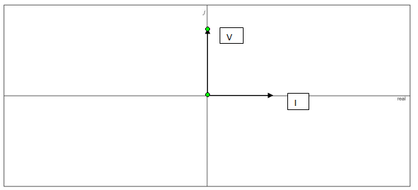
Fig. 15.84
Expert Solution & Answer
Want to see the full answer?
Check out a sample textbook solution
Students have asked these similar questions
Solve it fast plz
An inductor L is connected in parallel to the series combination of capacitor C and resistor R. If L = 0.02122 H, C = 0.000421 F and R = 5 Ω, the impressed voltage E = 120 volts AC. Find the following:
a. Circuit Diagram, total impedance, total current.
b. Determine the frequency at which the inductive reactance is equal to capacitive reactance.
c. Determine the voltage drop across the capacitor and the Quality Factor Q.
Find the inductive reactance of a 50 uH and 25 uH connected in parallel subjected to a 47.74648292 Hz.
Chapter 15 Solutions
Laboratory Manual for Introductory Circuit Analysis
Ch. 15 - For the resistive element in Fig. 15.81: Write the...Ch. 15 - For the resistive element in Fig. 15.82: Write the...Ch. 15 - For the inductive element of Fig. 15.83: a. Write...Ch. 15 - For the inductive element of Fig. 15.84: Calculate...Ch. 15 - For the inductive element of Fig. 15.85: Write the...Ch. 15 - For the capacitive element of Fig. 15.86: Write...Ch. 15 - For the capacitive element of Fig. 15.87:...Ch. 15 - For the capacitive element of Fig. 15.88: Write...Ch. 15 - Sketch the impedance diagram of a 120 k resistor.Ch. 15 - Sketch the impedance diagram of a 5 mH coil...
Ch. 15 - Sketch the impedance diagram of a 0.02 F capacitor...Ch. 15 - Calculate the total impedance of the circuits in...Ch. 15 - Calculate the total impedance of the circuits in...Ch. 15 - Find the type and impedance in ohms of the series...Ch. 15 - For the circuit in Fig. 15.92 Find the total...Ch. 15 - Repeat problem 15 for the circuit in Fig. 15.93,...Ch. 15 - For the circuit in Fig. 15.94: Find the total...Ch. 15 - Repeat Problem 17 for the circuit in Fig. 15.95...Ch. 15 - For the circuit of Fig. 15.96: Find the total...Ch. 15 - For the circuit of Fig. 15.97: Find the current...Ch. 15 - Prob. 21PCh. 15 - Using the oscilloscope reading in Fig. 15.99,...Ch. 15 - Using the DMM current reading and the oscilloscope...Ch. 15 - Using the oscilloscope reading in Fig. 15.101:...Ch. 15 - An electrical load has a power factor of 0.8...Ch. 15 - Find the series element or elements that must be...Ch. 15 - Calculate the voltages V1andV2 for the circuits in...Ch. 15 - Calculate the voltages V1andV2 for the circuits in...Ch. 15 - For the circuit in Fig. 15.105: Determine...Ch. 15 - For the circuit in Fig. 15.106: a. Plot ZT and T...Ch. 15 - Prob. 31PCh. 15 - For the series R-L-C circuit in Fig. 15.108: Plot...Ch. 15 - For the series R-C circuit in Fig. 15.109:...Ch. 15 - For the circuit in Fig. 15.110, determine the...Ch. 15 - For the oscilloscope traces in Fig. 15.111:...Ch. 15 - For the network in Fig. 15.92 (usef=1kHz):...Ch. 15 - For the network in Fig. 15.93: Plot the impedance...Ch. 15 - For the network in Fig. 15.105: Find the rms...
Additional Engineering Textbook Solutions
Find more solutions based on key concepts
For the “tank” circuit in Fig. 14.79, find the resonant frequency.
Figure 14.79
For Probs. 14.39, 14.71, and 1...
Fundamentals of Electric Circuits
Explain the main function of each of the following major components of a PLC: a. Processor module (CPU) b. I/O ...
Programmable Logic Controllers
Does the severity of an electric shock increase ordecrease with eh of the following changes? a. A decrease in t...
Electric Motors and Control Systems
Find I0 and I1 in the circuit in Fig.P2.12.
Basic Engineering Circuit Analysis
When travelers from the USA and Canada visit Europe, they encounter a different power distribution system. Wall...
Electric machinery fundamentals
What is the color code for a 365- five-band precision resistor with a tolerance of 5 percent?
ELECTRICITY FOR TRADES (LOOSELEAF)
Knowledge Booster


Learn more about
Need a deep-dive on the concept behind this application? Look no further. Learn more about this topic, electrical-engineering and related others by exploring similar questions and additional content below.Similar questions
- Calculation of inductive reactance...arrow_forwardMatch each quantity on the left to the correct units/dimensions shown on the right.arrow_forward5) Find the reactance the inductance and impedance of the circuit. Calculate the current of this circuit and the sketch waveform of current and voltage. V1 10 V 60 Hz R1 m 100kQ 12 Vrms 1000 Hz 0° 6) Find the reactance the inductance and impedance of the circuit. Calculate the currents of this circuit R www 502 L L1 106mH eee 10 mHarrow_forward
- Problem 5 Find the equivalent inductance Leg for the network shown below. 72 mH oooo Leg 49 mH elle elle 313 mH elle 64 mH elle 80 mHarrow_forwardWhat's 23arrow_forwardAn inductor of value 5.6 H is connected across 240 V, 109 Hz supply. Then the value of inductive reactance is ohms. 7666.62 1220.80 1916.66 3836.80arrow_forward
- I need help with this please.arrow_forwardQUESTION 3 An inductor, a capacitor, and a resistor are connected in parallel with a function generator. The inductor draws 100mA RMS, the capacitor draws 150mA RMS, and the resistor draws 200mA RMS. Find the magnitude of the total current. O 450mA RMS O 544mA RMS O 352mA RMS O 206mA RMSarrow_forwardb) A capacitor C is connected in series with a 40 O resistor across a supply of frequency 60 Hz. A current of 3A flows and the circuit impedance is 50 N, Calculate: (i) the value of capacitance, C, (ii) the supply voltage, (ii) the phase angle between the supply voltage and current, (iv) the p.d. across the resistor, (v) the p.d. across the capacitor.arrow_forward
- What's 21 22 23arrow_forwardExplain each of the following statements, whether true or false:a. The instantaneous voltage across the capacitor lags the current by 90°.b. The instantaneous voltage across the inductor leads the current by 90°.c. The instantaneous voltage across the resistor is in phase with the current.d. The voltages across the resistor, capacitor, and inductor are not in phase.e. The RMS voltage across the combination of the three elements equals the algebraic sum of the RMS voltages across each element separately.arrow_forward2, In a circuit, the capacitance of a capacitor is 3.2 microfarads and the rms voltage of the generator is 50 volts. Frequency (a) 100 Hz and (b) what is the rms current in the circuit when it is 1000 Hz?arrow_forward
arrow_back_ios
SEE MORE QUESTIONS
arrow_forward_ios
Recommended textbooks for you
 Introductory Circuit Analysis (13th Edition)Electrical EngineeringISBN:9780133923605Author:Robert L. BoylestadPublisher:PEARSON
 Delmar's Standard Textbook Of ElectricityElectrical EngineeringISBN:9781337900348Author:Stephen L. HermanPublisher:Cengage Learning
 Programmable Logic ControllersElectrical EngineeringISBN:9780073373843Author:Frank D. PetruzellaPublisher:McGraw-Hill Education
 Fundamentals of Electric CircuitsElectrical EngineeringISBN:9780078028229Author:Charles K Alexander, Matthew SadikuPublisher:McGraw-Hill Education
 Electric Circuits. (11th Edition)Electrical EngineeringISBN:9780134746968Author:James W. Nilsson, Susan RiedelPublisher:PEARSON
 Engineering ElectromagneticsElectrical EngineeringISBN:9780078028151Author:Hayt, William H. (william Hart), Jr, BUCK, John A.Publisher:Mcgraw-hill Education,
Introductory Circuit Analysis (13th Edition)
Electrical Engineering
ISBN:9780133923605
Author:Robert L. Boylestad
Publisher:PEARSON
Delmar's Standard Textbook Of Electricity
Electrical Engineering
ISBN:9781337900348
Author:Stephen L. Herman
Publisher:Cengage Learning
Programmable Logic Controllers
Electrical Engineering
ISBN:9780073373843
Author:Frank D. Petruzella
Publisher:McGraw-Hill Education
Fundamentals of Electric Circuits
Electrical Engineering
ISBN:9780078028229
Author:Charles K Alexander, Matthew Sadiku
Publisher:McGraw-Hill Education
Electric Circuits. (11th Edition)
Electrical Engineering
ISBN:9780134746968
Author:James W. Nilsson, Susan Riedel
Publisher:PEARSON
Engineering Electromagnetics
Electrical Engineering
ISBN:9780078028151
Author:Hayt, William H. (william Hart), Jr, BUCK, John A.
Publisher:Mcgraw-hill Education,
02 - Sinusoidal AC Voltage Sources in Circuits, Part 1; Author: Math and Science;https://www.youtube.com/watch?v=8zMiIHVMfaw;License: Standard Youtube License