
Laboratory Manual for Introductory Circuit Analysis
13th Edition
ISBN: 9780133923780
Author: Robert L. Boylestad, Gabriel Kousourou
Publisher: PEARSON
expand_more
expand_more
format_list_bulleted
Videos
Textbook Question
Chapter 15, Problem 23P
Using the DMM current reading and the oscilloscope measurement in Fig. 15.100:
- Determine the inductance L.
- Find the resistance R.
- Find the closest standard value for the inductance found in part (a).
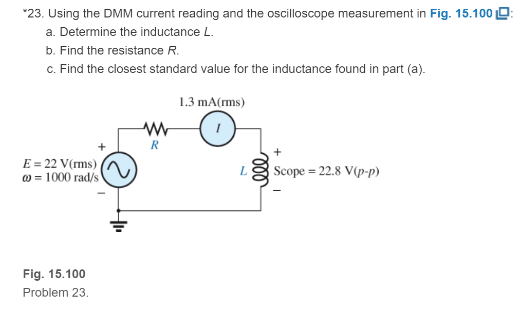
Fig. 15.100
Expert Solution & Answer
Want to see the full answer?
Check out a sample textbook solution
Students have asked these similar questions
b) A capacitor C is connected in series with a 40 O resistor across a supply of
frequency 60 Hz. A current of 3A flows and the circuit impedance is 50 N,
Calculate: (i) the value of capacitance, C, (ii) the supply voltage, (ii) the phase
angle between the supply voltage and current, (iv) the p.d. across the resistor, (v)
the p.d. across the capacitor.
Ministry of Manpower
Directorate General of Technological Education
Salalah College of Technology
Zlectrical Inginearina
Problem - 8
Refer to the circuit below and
-25V
C2
N. compute the following:
i) Total capacitance
ii) Voltage across C,
iii)Charge across C,
iv)Voltage across C5
5 uF
C1
5 uF
5 uF
C4
5 uF
C6
5 uF
-16-65V.
C5
5 uF
(Take V, as 25V)
8-35V
VT 25V
Given the circuit below
a. Find the MAGNITUDE of the current through the capacitor (express answer in mA with 2 decimal places)
b. Find the MAGNITUDE of the current through the inductor (express answer in mA with 2 decimal places)
c. Find the MAGNITUDE of the total real power (express answer in WATTS with 2 decimal places)
d. Find the MAGNITUDE of the total reactive power (express answer in VARS with 2 decimal places)
e. Find the MAGNITUDE of the total impedance (express answer in ohms with 2 decimal places)
Chapter 15 Solutions
Laboratory Manual for Introductory Circuit Analysis
Ch. 15 - For the resistive element in Fig. 15.81: Write the...Ch. 15 - For the resistive element in Fig. 15.82: Write the...Ch. 15 - For the inductive element of Fig. 15.83: a. Write...Ch. 15 - For the inductive element of Fig. 15.84: Calculate...Ch. 15 - For the inductive element of Fig. 15.85: Write the...Ch. 15 - For the capacitive element of Fig. 15.86: Write...Ch. 15 - For the capacitive element of Fig. 15.87:...Ch. 15 - For the capacitive element of Fig. 15.88: Write...Ch. 15 - Sketch the impedance diagram of a 120 k resistor.Ch. 15 - Sketch the impedance diagram of a 5 mH coil...
Ch. 15 - Sketch the impedance diagram of a 0.02 F capacitor...Ch. 15 - Calculate the total impedance of the circuits in...Ch. 15 - Calculate the total impedance of the circuits in...Ch. 15 - Find the type and impedance in ohms of the series...Ch. 15 - For the circuit in Fig. 15.92 Find the total...Ch. 15 - Repeat problem 15 for the circuit in Fig. 15.93,...Ch. 15 - For the circuit in Fig. 15.94: Find the total...Ch. 15 - Repeat Problem 17 for the circuit in Fig. 15.95...Ch. 15 - For the circuit of Fig. 15.96: Find the total...Ch. 15 - For the circuit of Fig. 15.97: Find the current...Ch. 15 - Prob. 21PCh. 15 - Using the oscilloscope reading in Fig. 15.99,...Ch. 15 - Using the DMM current reading and the oscilloscope...Ch. 15 - Using the oscilloscope reading in Fig. 15.101:...Ch. 15 - An electrical load has a power factor of 0.8...Ch. 15 - Find the series element or elements that must be...Ch. 15 - Calculate the voltages V1andV2 for the circuits in...Ch. 15 - Calculate the voltages V1andV2 for the circuits in...Ch. 15 - For the circuit in Fig. 15.105: Determine...Ch. 15 - For the circuit in Fig. 15.106: a. Plot ZT and T...Ch. 15 - Prob. 31PCh. 15 - For the series R-L-C circuit in Fig. 15.108: Plot...Ch. 15 - For the series R-C circuit in Fig. 15.109:...Ch. 15 - For the circuit in Fig. 15.110, determine the...Ch. 15 - For the oscilloscope traces in Fig. 15.111:...Ch. 15 - For the network in Fig. 15.92 (usef=1kHz):...Ch. 15 - For the network in Fig. 15.93: Plot the impedance...Ch. 15 - For the network in Fig. 15.105: Find the rms...
Knowledge Booster


Learn more about
Need a deep-dive on the concept behind this application? Look no further. Learn more about this topic, electrical-engineering and related others by exploring similar questions and additional content below.Similar questions
- S. Inductancearrow_forwardAn inductor L is connected in parallel to the series combination of capacitor C and resistor R. If L = 0.02122 H, C = 0.000421 F and R = 5 Ω, the impressed voltage E = 120 volts AC. Find the following: a. Circuit Diagram, total impedance, total current. b. Determine the frequency at which the inductive reactance is equal to capacitive reactance. c. Determine the voltage drop across the capacitor and the Quality Factor Q.arrow_forwardAC 15. What would the equivalent resistance be of a 159 uF capacitor? 16. What is the RMS voltage of a circuit if the peak voltage is 170 volts? 17. If the RMS voltage is 240 volts AC, what is the peak voltage? 18. What is the formula for finding an inductors equivalent resistance? 19. What is the equivalent resistance of an inductor with 0.17 henrys? 20. What is the symbol of an AC power source? 21. What is the equivalent inductance of a parallel circuit with a 0.01L, 0.02L, and 1.7L inductor? 22. What is the equivalent inductance of a series circuit with a 0.03L, 0.04L, and 1.6L inductor? 23. A transformer with a primary voltage of 480 volts and a turns ratio of 2:1 will have what secondary voltage? 24. A Power Network is comprised of what three components? 25. What is the main difference between a fuse and a circuit breaker?arrow_forward
- Q19. Four capacitors of lµF, 3µF,5µF and 6µF are connected in series across 360V AC supply. Evaluate the following: i. Equivalent Capacitance in terms of uF ii. Charge on each capacitor in terms of µC iii. Voltage across each capacitor.arrow_forwardFind the following. A, the phase angle between the supply voltage and current. B, the voltage across the inductor coil. C, voltage across the capacitor.arrow_forwardProblem 15. A capacitor is to be constructed so that its capacitance is 0.2 pF and to take a p.d. of 1.25 kV across its terminals. The dielectric is to be mica which, after allowing a safety factor of 2, has a dielectric strength of 50 MV/m. Find (a) the thickness of the mica needed, and (b) the area of a plate assuming a two-plate construction. (Assume e, for mica to be 6).arrow_forward
- Fundamentals of Electrical Engineering 2020/2021 Dr. Yaseen H. Tahir xample: (example 15-3, page 388, David) (H. W.) A 1 MF capacitance is to be constructed from rolled-up sheets of aluminum foil separated by a layer of paper 0.1 mm thick. Calculate the required area for each sheet of foil if the relative permittivity of the paper is 6. Jution:arrow_forwardFind the inductive reactance of a 50 uH and 25 uH connected in parallel subjected to a 47.74648292 Hz.arrow_forwardECE 20 CW1-1 12 Vrms ↓ 177 a) what is the load voltage ? b) If the capacitor is open- what's the load voltage?arrow_forward
- Determine the capacitance value if the capacitive reactance of 15 Kohms operates on a 40 Hz supply. a. 2.652 micro farad O b. 26.52 micro farad O c. 0.2652 MF d. 0.2652 micro faradarrow_forwardDetermine R, so that it absorbs m.p.tarrow_forwardIf the input voltage for the given circuit below is 220 V at 50 Hz, the load resistance (RL) is 3300 and the average output voltage is 20 V. Assume the diodes to be germanium diodes. Determine the turns ratio of the transformer used. If a capacitor of 100 µF is connected parallel to the load resistor (RL), Determine the ripple factor. D1 D2 V D3 .... D4 RL a. The turns ratio of transformer (Npri/Nsec) is b. The Ripple factor is cell rellarrow_forward
arrow_back_ios
SEE MORE QUESTIONS
arrow_forward_ios
Recommended textbooks for you

Resonance Circuits: LC Inductor-Capacitor Resonating Circuits; Author: Physics Videos by Eugene Khutoryansky;https://www.youtube.com/watch?v=Mq-PF1vo9QA;License: Standard YouTube License, CC-BY