
Laboratory Manual for Introductory Circuit Analysis
13th Edition
ISBN: 9780133923780
Author: Robert L. Boylestad, Gabriel Kousourou
Publisher: PEARSON
expand_more
expand_more
format_list_bulleted
Concept explainers
Videos
Textbook Question
Chapter 15, Problem 5P
For the inductive element of Fig. 15.85:
- Write the voltage and current in phasor form.
- Calculate the impedance of the inductor.
- Find the inductance of the coil.
- Sketch the phasor diagram of the voltage and current.
- Sketch the waveform of the voltage and current.
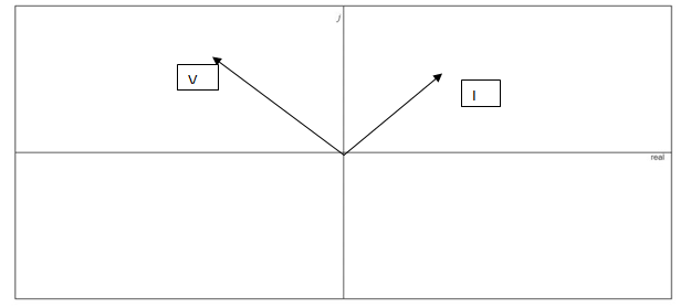
Fig. 15.85
Expert Solution & Answer
Want to see the full answer?
Check out a sample textbook solution
Students have asked these similar questions
Find the inductive reactance of a 50 uH and 25 uH connected in parallel subjected to a 47.74648292 Hz.
2. A coil, having a resistance of 100 2 and an inductance of 0.2 H, is connected in series
with a 20 µF capacitor across a 120 V, 60 Hz supply. Determine:
a. the impedance of the circuit.
b. the current.
c. the power factor of the circuit.
d. the voltage across the capacitor.
e. the instantaneous maximum voltage across the terminals of the capacitor.
Determine the capacitance value if the capacitive
reactance of 15 Kohms operates on a 40 Hz
supply.
a. 2.652 micro farad
O b. 26.52 micro farad
O c. 0.2652 MF
d. 0.2652 micro farad
Chapter 15 Solutions
Laboratory Manual for Introductory Circuit Analysis
Ch. 15 - For the resistive element in Fig. 15.81: Write the...Ch. 15 - For the resistive element in Fig. 15.82: Write the...Ch. 15 - For the inductive element of Fig. 15.83: a. Write...Ch. 15 - For the inductive element of Fig. 15.84: Calculate...Ch. 15 - For the inductive element of Fig. 15.85: Write the...Ch. 15 - For the capacitive element of Fig. 15.86: Write...Ch. 15 - For the capacitive element of Fig. 15.87:...Ch. 15 - For the capacitive element of Fig. 15.88: Write...Ch. 15 - Sketch the impedance diagram of a 120 k resistor.Ch. 15 - Sketch the impedance diagram of a 5 mH coil...
Ch. 15 - Sketch the impedance diagram of a 0.02 F capacitor...Ch. 15 - Calculate the total impedance of the circuits in...Ch. 15 - Calculate the total impedance of the circuits in...Ch. 15 - Find the type and impedance in ohms of the series...Ch. 15 - For the circuit in Fig. 15.92 Find the total...Ch. 15 - Repeat problem 15 for the circuit in Fig. 15.93,...Ch. 15 - For the circuit in Fig. 15.94: Find the total...Ch. 15 - Repeat Problem 17 for the circuit in Fig. 15.95...Ch. 15 - For the circuit of Fig. 15.96: Find the total...Ch. 15 - For the circuit of Fig. 15.97: Find the current...Ch. 15 - Prob. 21PCh. 15 - Using the oscilloscope reading in Fig. 15.99,...Ch. 15 - Using the DMM current reading and the oscilloscope...Ch. 15 - Using the oscilloscope reading in Fig. 15.101:...Ch. 15 - An electrical load has a power factor of 0.8...Ch. 15 - Find the series element or elements that must be...Ch. 15 - Calculate the voltages V1andV2 for the circuits in...Ch. 15 - Calculate the voltages V1andV2 for the circuits in...Ch. 15 - For the circuit in Fig. 15.105: Determine...Ch. 15 - For the circuit in Fig. 15.106: a. Plot ZT and T...Ch. 15 - Prob. 31PCh. 15 - For the series R-L-C circuit in Fig. 15.108: Plot...Ch. 15 - For the series R-C circuit in Fig. 15.109:...Ch. 15 - For the circuit in Fig. 15.110, determine the...Ch. 15 - For the oscilloscope traces in Fig. 15.111:...Ch. 15 - For the network in Fig. 15.92 (usef=1kHz):...Ch. 15 - For the network in Fig. 15.93: Plot the impedance...Ch. 15 - For the network in Fig. 15.105: Find the rms...
Additional Engineering Textbook Solutions
Find more solutions based on key concepts
Find I0 and I1 in the circuit in Fig.P2.12.
Basic Engineering Circuit Analysis
Design an ideal inverting op-amp circuit such that the voltage gain is Av=25 . The maximum current in any resis...
Microelectronics: Circuit Analysis and Design
A constant voltage of 10V is applied to a 50H inductance, as shown in Figure P3.51 Figure P3 51 The current in ...
Electrical Engineering: Principles & Applications (7th Edition)
With respect to the circuit in Fig. 5.90, (a) employ Thévenin’s theorem to determine the equivalent network see...
Loose Leaf for Engineering Circuit Analysis Format: Loose-leaf
Electric power systems provide energy in a variety of commercial and industrial settings. Make a list of system...
Principles and Applications of Electrical Engineering
The current source in the circuit shown generates the current pulse
Find (a) v (0); (b) the instant of time gr...
Electric Circuits. (11th Edition)
Knowledge Booster


Learn more about
Need a deep-dive on the concept behind this application? Look no further. Learn more about this topic, electrical-engineering and related others by exploring similar questions and additional content below.Similar questions
- Find the equivalent inductive reactance if the frequency is 61 Hz. ... a m IH L, C 6 H L, 3 6 H L,R 4 H 2 H зн Round your answer to 2 decimal places.arrow_forward5.) Calculate the inductance or capacitance in series for the impedance 502-60° ohms. Assume the frequency to be 50 Hz. Express in four decimal places.arrow_forwardImpedance of AC circuit and Admittance of AC circuitSHOW THE CIRCUIT USING ANY SOFTWARE OR YOU CAN DRAW IT MANUAALYY thNAKSSarrow_forward
- 5) Find the reactance the inductance and impedance of the circuit. Calculate the current of this circuit and the sketch waveform of current and voltage. V1 10 V 60 Hz R1 m 100kQ 12 Vrms 1000 Hz 0° 6) Find the reactance the inductance and impedance of the circuit. Calculate the currents of this circuit R www 502 L L1 106mH eee 10 mHarrow_forwardd. What is the phasor and instantaneous voltage across the capacitor? e. If a 75μF capacitor is shunted across the load, what is now the value of the equivalent impedance in the connection?arrow_forward10. Two reactors are connected in series across a 10 V, 10 kHz source. They are spaced so that there is no interaction between their electromagnetic fields. Coil 1 has an effective resistance of 200 22 and an inductance of 200 mH. Coil 2 has an effective resistance of 300 2 and an inductance of 10 mH. Determine: a. the total resistance, in ohms. b. the total inductive reactance, in ohms. c. the total impedance, in ohms. d. the current, in milliamperes. e. the total true power expended in the series circuit, in watts.arrow_forward
- A 127 uf capacitor is connected to a 125V 50 cycle source . Calculate (a) the capacitive reactance (b)the current in the circuit, (c) the average power taken by the capacitor(d) the maximum power delivered to the capacitor returned to the source. (e) write the equation of the current, (f) the equation of the power?arrow_forwardWhat is the reactance of 3.00 microfarad capacitor? What is the impedance of the capacitor in series of 300 ohms?arrow_forwardA 5 ohm resistor in series with an inductor having an inductance of L = 15.92 mH is connected to a voltage sourceof 110 volts 60 Hz. Determine the true power consumed by the load.arrow_forward
- An inductive reactance of 6 ohm is connected in series with a parallel combination of a variable resistor R and a capacitive reactance of 15 ohm across 100V , 50 hz supply. a. Solve for the frequency so that the magnitude of the inductive reactance is 2 times the magnitude of capacitive reactance. b. Solve for the value of R so that the total current I will be maximum.arrow_forwardFind the total inductance for all Scircuits Do not forget units. 14 410 LI9 112 413 417 121arrow_forward. A coil, having resistance and inductance, has Z 50 2 and the phase angle of the current through it with respect to the voltage across it is 45° lag. The coil is connected in series with a 40 N resistor across AC supply. The circuit current is 3A. Find (i) supply voltage and (ii) circuit phase angle.arrow_forward
arrow_back_ios
SEE MORE QUESTIONS
arrow_forward_ios
Recommended textbooks for you
 Introductory Circuit Analysis (13th Edition)Electrical EngineeringISBN:9780133923605Author:Robert L. BoylestadPublisher:PEARSON
 Delmar's Standard Textbook Of ElectricityElectrical EngineeringISBN:9781337900348Author:Stephen L. HermanPublisher:Cengage Learning
 Programmable Logic ControllersElectrical EngineeringISBN:9780073373843Author:Frank D. PetruzellaPublisher:McGraw-Hill Education
 Fundamentals of Electric CircuitsElectrical EngineeringISBN:9780078028229Author:Charles K Alexander, Matthew SadikuPublisher:McGraw-Hill Education
 Electric Circuits. (11th Edition)Electrical EngineeringISBN:9780134746968Author:James W. Nilsson, Susan RiedelPublisher:PEARSON
 Engineering ElectromagneticsElectrical EngineeringISBN:9780078028151Author:Hayt, William H. (william Hart), Jr, BUCK, John A.Publisher:Mcgraw-hill Education,
Introductory Circuit Analysis (13th Edition)
Electrical Engineering
ISBN:9780133923605
Author:Robert L. Boylestad
Publisher:PEARSON
Delmar's Standard Textbook Of Electricity
Electrical Engineering
ISBN:9781337900348
Author:Stephen L. Herman
Publisher:Cengage Learning
Programmable Logic Controllers
Electrical Engineering
ISBN:9780073373843
Author:Frank D. Petruzella
Publisher:McGraw-Hill Education
Fundamentals of Electric Circuits
Electrical Engineering
ISBN:9780078028229
Author:Charles K Alexander, Matthew Sadiku
Publisher:McGraw-Hill Education
Electric Circuits. (11th Edition)
Electrical Engineering
ISBN:9780134746968
Author:James W. Nilsson, Susan Riedel
Publisher:PEARSON
Engineering Electromagnetics
Electrical Engineering
ISBN:9780078028151
Author:Hayt, William H. (william Hart), Jr, BUCK, John A.
Publisher:Mcgraw-hill Education,
Diodes Explained - The basics how diodes work working principle pn junction; Author: The Engineering Mindset;https://www.youtube.com/watch?v=Fwj_d3uO5g8;License: Standard Youtube License