
Laboratory Manual for Introductory Circuit Analysis
13th Edition
ISBN: 9780133923780
Author: Robert L. Boylestad, Gabriel Kousourou
Publisher: PEARSON
expand_more
expand_more
format_list_bulleted
Concept explainers
Videos
Textbook Question
Chapter 15, Problem 24P
Using the oscilloscope reading in Fig. 15.101:
- Find the rms value of the current in the series circuit.
- Determine the capacitance C.
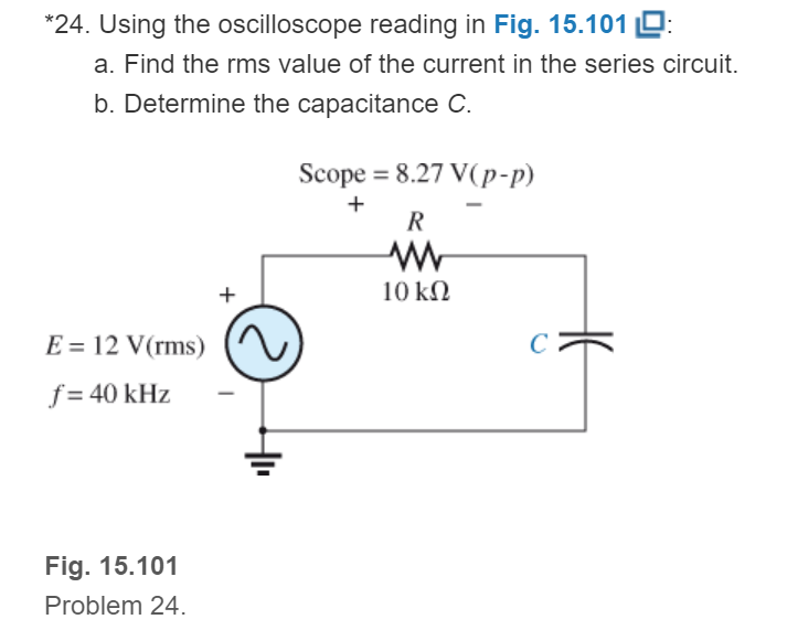
Fig. 15.101
Expert Solution & Answer
Want to see the full answer?
Check out a sample textbook solution
Students have asked these similar questions
solve for the total complex, apparent, average, and reactive power
solve for the total complex, apparent, average, and reactive power. sketch the power triangle
a) Determine the resistance and series inductance or capacitance for
each of the following impedances, assuing a frequency of 50HZ
i.
(4.0+ j7.0)z
CR (4)
154-60°z
Chapter 15 Solutions
Laboratory Manual for Introductory Circuit Analysis
Ch. 15 - For the resistive element in Fig. 15.81: Write the...Ch. 15 - For the resistive element in Fig. 15.82: Write the...Ch. 15 - For the inductive element of Fig. 15.83: a. Write...Ch. 15 - For the inductive element of Fig. 15.84: Calculate...Ch. 15 - For the inductive element of Fig. 15.85: Write the...Ch. 15 - For the capacitive element of Fig. 15.86: Write...Ch. 15 - For the capacitive element of Fig. 15.87:...Ch. 15 - For the capacitive element of Fig. 15.88: Write...Ch. 15 - Sketch the impedance diagram of a 120 k resistor.Ch. 15 - Sketch the impedance diagram of a 5 mH coil...
Ch. 15 - Sketch the impedance diagram of a 0.02 F capacitor...Ch. 15 - Calculate the total impedance of the circuits in...Ch. 15 - Calculate the total impedance of the circuits in...Ch. 15 - Find the type and impedance in ohms of the series...Ch. 15 - For the circuit in Fig. 15.92 Find the total...Ch. 15 - Repeat problem 15 for the circuit in Fig. 15.93,...Ch. 15 - For the circuit in Fig. 15.94: Find the total...Ch. 15 - Repeat Problem 17 for the circuit in Fig. 15.95...Ch. 15 - For the circuit of Fig. 15.96: Find the total...Ch. 15 - For the circuit of Fig. 15.97: Find the current...Ch. 15 - Prob. 21PCh. 15 - Using the oscilloscope reading in Fig. 15.99,...Ch. 15 - Using the DMM current reading and the oscilloscope...Ch. 15 - Using the oscilloscope reading in Fig. 15.101:...Ch. 15 - An electrical load has a power factor of 0.8...Ch. 15 - Find the series element or elements that must be...Ch. 15 - Calculate the voltages V1andV2 for the circuits in...Ch. 15 - Calculate the voltages V1andV2 for the circuits in...Ch. 15 - For the circuit in Fig. 15.105: Determine...Ch. 15 - For the circuit in Fig. 15.106: a. Plot ZT and T...Ch. 15 - Prob. 31PCh. 15 - For the series R-L-C circuit in Fig. 15.108: Plot...Ch. 15 - For the series R-C circuit in Fig. 15.109:...Ch. 15 - For the circuit in Fig. 15.110, determine the...Ch. 15 - For the oscilloscope traces in Fig. 15.111:...Ch. 15 - For the network in Fig. 15.92 (usef=1kHz):...Ch. 15 - For the network in Fig. 15.93: Plot the impedance...Ch. 15 - For the network in Fig. 15.105: Find the rms...
Additional Engineering Textbook Solutions
Find more solutions based on key concepts
A constant voltage of 10V is applied to a 50H inductance, as shown in Figure P3.51 Figure P3 51 The current in ...
Electrical Engineering: Principles & Applications (7th Edition)
Three point charges of equal magnitude q, that will yield a zero net electric field at the origin.
Engineering Electromagnetics
Design an ideal inverting op-amp circuit such that the voltage gain is Av=25 . The maximum current in any resis...
Microelectronics: Circuit Analysis and Design
Explain the main function of each of the following major components of a PLC: a. Processor module (CPU) b. I/O ...
Programmable Logic Controllers
Analog Voltmeter Design Figure P2-98(a) shows a voltmeter circuit consisting of a D'Arsonval meter, two series ...
ANALYSIS+DESIGN OF LINEAR CIRCUITS(LL)
Identify the type of input and output configuration for each diff-amp in Figure 18-35.
Electronics Fundamentals: Circuits, Devices & Applications
Knowledge Booster


Learn more about
Need a deep-dive on the concept behind this application? Look no further. Learn more about this topic, electrical-engineering and related others by exploring similar questions and additional content below.Similar questions
- a) Find the phasor current I. Enter your answer using polar notation. b) Find the power delivered by the source and the reactive power delivered by the source. c) Find the apparent power delivered by the source and the power factorarrow_forward4. a) Find the equivalent impedance between terminals A and B for the following circuit at a frequency of 50HZ. 0.0191 H I, 50 0.0318 H A ww 398 µF (Z) b) Find the average value of the following current waveform 2n 0- 3tarrow_forwardThe cosine of the phase difference between voltage and current defines a) The magnitude of the reactive power. b) The magnitude of the apparent power c) The power factor. d) None of the abovearrow_forward
- Determine the capacitance value if the capacitive reactance of 15 Kohms operates on a 40 Hz supply. a. 2.652 micro farad O b. 26.52 micro farad O c. 0.2652 MF d. 0.2652 micro faradarrow_forwardDetermine the Inductance that has a Reactance of 2 KOhms, at a frequency of 14.47 KHz. show all the stepsarrow_forwarda sinusoidal source supplies 10kVA to a load Z=250Ω∠-75°. Determine (a) the power factor. (b) the reactive power delivered by the load and (c) the maximum voltagearrow_forward
- 58. Two capacitors, a 20 µF and a 30 µF, are connected in series to a 60-Hz source. What is the total capacitive reactance? a. 117.96 N b. 221.04 N c. 253.05 N d. 333.16 Narrow_forwardAn rms voltage of 22.2 V with a frequencyof 1.00 kHz is applied to a 0.290-mH inductor. (a) What is the rmscurrent in this circuit? (b) By what factor does the current changeif the frequency of the voltage is doubled? (c) Calculate the current for a frequency of 2.00 kHzarrow_forward:D A docs.google.com/forms/d/1 o المرحلة والشعبة: * A non-sinusoidal voltage (e=20+15sin1000t+ 10sin3000t+5sin4000t) Volt is applied to the circuit shown. Find the ?total power iT 42 İL -J92 J42 44.03 W 86.08 W 88.06 W 44.04 W n-sinusoidal wave can be طلب الإذن بالتعديل of sine waves with .harmonic frequencies IIarrow_forward
- The voltage applied to a purely inductive coil of self-inductance 15.9 mH is given by the equation v = 100 sin 314t + 75 sin 942t + 50 sm 1570t . Find the equation of the resulting current wave.arrow_forward2. In your own words, explain : a. What is reactive power? b. What is average power? c. What is instantaneous power? 3. For Fig 1 is shown a pure resistive circuit. Discovery wave-generator values and resistors acquired with your components kit. Average power must be P=13mW. Vin must be less than 5Vpp. Choose one value and get the Vrms for your calculations. Design the circuit according to your Analog Vin= Vrms 1000 Hz R1 0° Fig 1 a. What is R1 value? b. What is Vp value? What is Vpp value? С. d. What is Vrms value? e. Show your calculations and equations used.arrow_forwardAn AC Voltage Generator provides 100 V at angular frequency of 500 rad/s to a series RLC, R = 3 ohms, C = 50 uF, L = 10 to 80 mH. Peak Voltage across the capacitor should not exceed 1200 V. A. Determine the AC Source, V(t) and I(t). B. Determine the voltage across the Resistor, VR(t). VR(t) is in phase with I(t). C. What is the average voltage across the resistor, VR?arrow_forward
arrow_back_ios
SEE MORE QUESTIONS
arrow_forward_ios
Recommended textbooks for you
 Introductory Circuit Analysis (13th Edition)Electrical EngineeringISBN:9780133923605Author:Robert L. BoylestadPublisher:PEARSON
 Delmar's Standard Textbook Of ElectricityElectrical EngineeringISBN:9781337900348Author:Stephen L. HermanPublisher:Cengage Learning
 Programmable Logic ControllersElectrical EngineeringISBN:9780073373843Author:Frank D. PetruzellaPublisher:McGraw-Hill Education
 Fundamentals of Electric CircuitsElectrical EngineeringISBN:9780078028229Author:Charles K Alexander, Matthew SadikuPublisher:McGraw-Hill Education
 Electric Circuits. (11th Edition)Electrical EngineeringISBN:9780134746968Author:James W. Nilsson, Susan RiedelPublisher:PEARSON
 Engineering ElectromagneticsElectrical EngineeringISBN:9780078028151Author:Hayt, William H. (william Hart), Jr, BUCK, John A.Publisher:Mcgraw-hill Education,
Introductory Circuit Analysis (13th Edition)
Electrical Engineering
ISBN:9780133923605
Author:Robert L. Boylestad
Publisher:PEARSON
Delmar's Standard Textbook Of Electricity
Electrical Engineering
ISBN:9781337900348
Author:Stephen L. Herman
Publisher:Cengage Learning
Programmable Logic Controllers
Electrical Engineering
ISBN:9780073373843
Author:Frank D. Petruzella
Publisher:McGraw-Hill Education
Fundamentals of Electric Circuits
Electrical Engineering
ISBN:9780078028229
Author:Charles K Alexander, Matthew Sadiku
Publisher:McGraw-Hill Education
Electric Circuits. (11th Edition)
Electrical Engineering
ISBN:9780134746968
Author:James W. Nilsson, Susan Riedel
Publisher:PEARSON
Engineering Electromagnetics
Electrical Engineering
ISBN:9780078028151
Author:Hayt, William H. (william Hart), Jr, BUCK, John A.
Publisher:Mcgraw-hill Education,
What is Filter & Classification of Filters | Four Types of Filters | Electronic Devices & Circuits; Author: SimplyInfo;https://www.youtube.com/watch?v=9x1Sjz-VPSg;License: Standard Youtube License