
Laboratory Manual for Introductory Circuit Analysis
13th Edition
ISBN: 9780133923780
Author: Robert L. Boylestad, Gabriel Kousourou
Publisher: PEARSON
expand_more
expand_more
format_list_bulleted
Videos
Textbook Question
Chapter 15, Problem 27P
Calculate the voltages
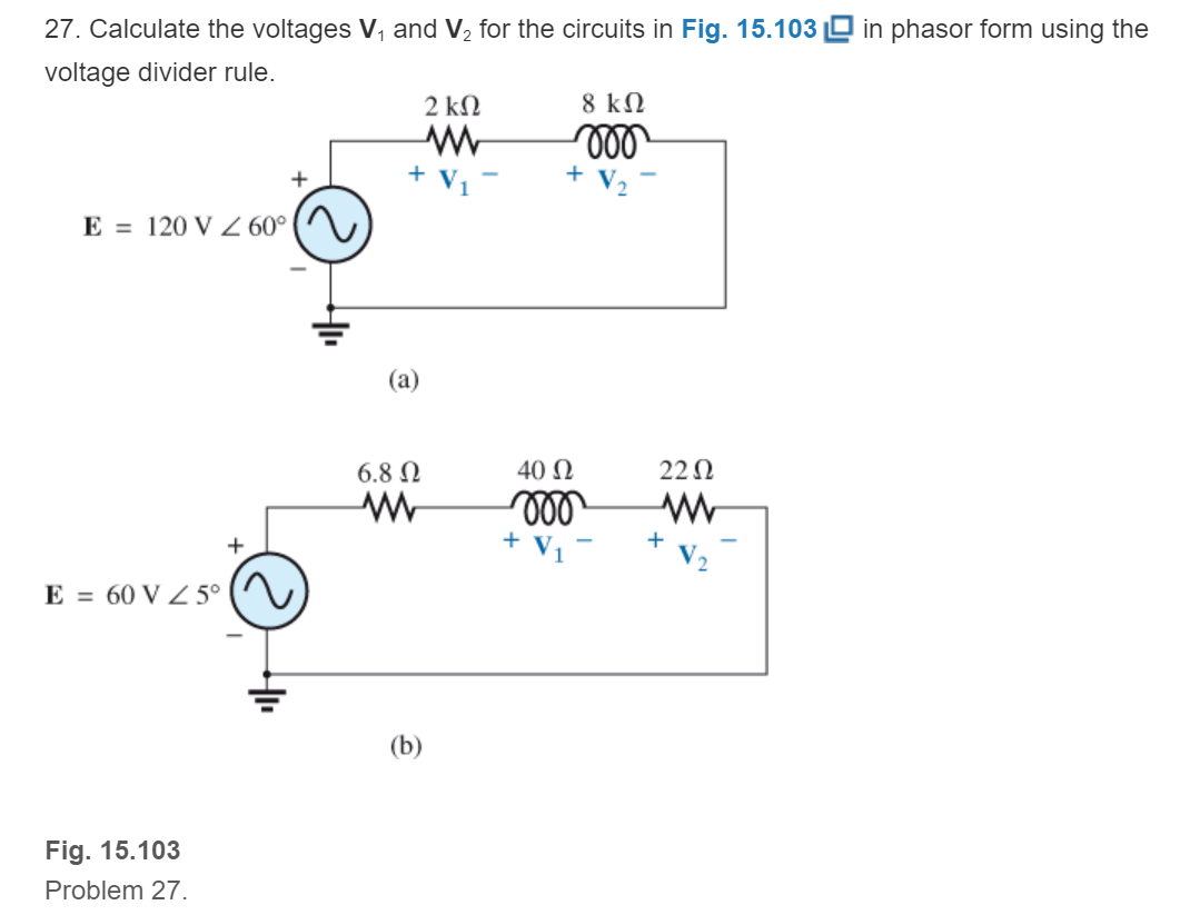
Fig. 15.103
Expert Solution & Answer
Want to see the full answer?
Check out a sample textbook solution
Students have asked these similar questions
4) Calculate the current through Ci (lci).
R1
2200
www.
15VRMS
25 kHz
R2
390 Ω
L1
0.5mH
• MooM
L2
2mH
IC₁ =
C1
0.01μF
C2
1800pF
For all problems, solve for the following
a. Vgs
b. Id
16V
C.
Zin
d. Zout
e. Av
¹3.9kQ
V₁0
H
0.05 µF
IMQ
|
0.05 μF
HF
Joss - 6 MA
Vp-3 V
1.6 k
40µF
15:24
A
2. Calculate the total resistance between the points A and B.
3
-www
4 ohm
|||
www
3 ohm
Qall 72%
V
1 ohm
ww
2 ohm
0
Chapter 15 Solutions
Laboratory Manual for Introductory Circuit Analysis
Ch. 15 - For the resistive element in Fig. 15.81: Write the...Ch. 15 - For the resistive element in Fig. 15.82: Write the...Ch. 15 - For the inductive element of Fig. 15.83: a. Write...Ch. 15 - For the inductive element of Fig. 15.84: Calculate...Ch. 15 - For the inductive element of Fig. 15.85: Write the...Ch. 15 - For the capacitive element of Fig. 15.86: Write...Ch. 15 - For the capacitive element of Fig. 15.87:...Ch. 15 - For the capacitive element of Fig. 15.88: Write...Ch. 15 - Sketch the impedance diagram of a 120 k resistor.Ch. 15 - Sketch the impedance diagram of a 5 mH coil...
Ch. 15 - Sketch the impedance diagram of a 0.02 F capacitor...Ch. 15 - Calculate the total impedance of the circuits in...Ch. 15 - Calculate the total impedance of the circuits in...Ch. 15 - Find the type and impedance in ohms of the series...Ch. 15 - For the circuit in Fig. 15.92 Find the total...Ch. 15 - Repeat problem 15 for the circuit in Fig. 15.93,...Ch. 15 - For the circuit in Fig. 15.94: Find the total...Ch. 15 - Repeat Problem 17 for the circuit in Fig. 15.95...Ch. 15 - For the circuit of Fig. 15.96: Find the total...Ch. 15 - For the circuit of Fig. 15.97: Find the current...Ch. 15 - Prob. 21PCh. 15 - Using the oscilloscope reading in Fig. 15.99,...Ch. 15 - Using the DMM current reading and the oscilloscope...Ch. 15 - Using the oscilloscope reading in Fig. 15.101:...Ch. 15 - An electrical load has a power factor of 0.8...Ch. 15 - Find the series element or elements that must be...Ch. 15 - Calculate the voltages V1andV2 for the circuits in...Ch. 15 - Calculate the voltages V1andV2 for the circuits in...Ch. 15 - For the circuit in Fig. 15.105: Determine...Ch. 15 - For the circuit in Fig. 15.106: a. Plot ZT and T...Ch. 15 - Prob. 31PCh. 15 - For the series R-L-C circuit in Fig. 15.108: Plot...Ch. 15 - For the series R-C circuit in Fig. 15.109:...Ch. 15 - For the circuit in Fig. 15.110, determine the...Ch. 15 - For the oscilloscope traces in Fig. 15.111:...Ch. 15 - For the network in Fig. 15.92 (usef=1kHz):...Ch. 15 - For the network in Fig. 15.93: Plot the impedance...Ch. 15 - For the network in Fig. 15.105: Find the rms...
Knowledge Booster


Learn more about
Need a deep-dive on the concept behind this application? Look no further. Learn more about this topic, electrical-engineering and related others by exploring similar questions and additional content below.Similar questions
- [Q3] Analyze the following electrical circuit with mesh analysis by finding the currents using Gauss-elimination method 10 Q 15 Q 25 0 20Q 35Q - 1000 V 1000V 2000 V 2000 V 30 2 40 Qarrow_forward5 52 13 -j12 5:1 j2 12 ww 50 20 V 20 VI For the circuit shown, the value of the primary side of the ideal transformer V1 is .V. * O 34<98.1 O 67<58.1 O 104<-67.3 O 72<-45.3 O 48<86.7 O63<-54.3 O 56.4<87.3 O none of the above wwarrow_forwardA JFET has a value of gmo = 4000 μS. Determine the value of gm at VGS = – 3V. Given that VGS (off) = – 8V.arrow_forward
- For the circuit shown in the Figure, if Vs= 50 V and R = 105 Q, answer the following 2 questions: I com (A +V 3 KQ com 3 KO S6KO > 6 KO The reading of the ammeter A is: Oa. 15.84 mA Ob. 19.84 mA Oc. 17.84 mA Od. 21.84 mA The reading of the voltmeter V is: Оа. 3.9 V Ob. 2 V Ос. 3.12 V Od. 2.49 Varrow_forwardV 2A 8A 10 ohm O _60 O 40 O _40 60arrow_forwardBonomo Bulunmam G s/94048/quizzes/119102/take j3N 1179 20/150 } 19912 1172 20- 907 19912 20230° 1952 a)Ls yuk akımını bnlunuz (100 puan) b) Vac hal gerilimini veriniz(0 puan) c) Yukler üzerindekitoplamkompleks gücu hesaplavnez (10 puan) Kısa Sinavı G ASUS 14 f5 f6 f7 f8 f10arrow_forward
- kindly do this problemarrow_forwardWhich of the following is true for pure capacitive circuit? a. Current lags the voltage by 90 degree b. Voltage and current are inphase С. Voltage lags the current by 90 degree d. Voltage leads the current by 90 degree •A:Oarrow_forwardQuestion 13 For the circuit shown, the following mesh currents are given: IA =1.24271.2° A IB =0.45Z49.0° A Ic = 0.75Z150.2° A What is the value of the voltage VB? j5n + 20 VB 62- 45° V j4 N VA 240° V Vc 5230° V O 2.484- 108.8° V O 2.48471.2 V O 2.23/66.8° V O 2.23Z- 113.2° Varrow_forward
- Xc R1 XL 60 10 Ω 12 Ω Zt For the above serial components calculate the total impedance - Zt Zt = %3Darrow_forward3&page%3D1 American Uni. Girne American Uni.. O portal.gaueng.org My Profile - Zoom Dashboard My Courses This course Find the Norton equivalent of the circuit 60 30 40V ,50 202 A BI E E E E ere to searcharrow_forwardQ15. Find the voltage VA in the circuit shown below.I 9 20 V Si Ge 3 K2arrow_forward
arrow_back_ios
SEE MORE QUESTIONS
arrow_forward_ios
Recommended textbooks for you
 Power System Analysis and Design (MindTap Course ...Electrical EngineeringISBN:9781305632134Author:J. Duncan Glover, Thomas Overbye, Mulukutla S. SarmaPublisher:Cengage Learning
Power System Analysis and Design (MindTap Course ...
Electrical Engineering
ISBN:9781305632134
Author:J. Duncan Glover, Thomas Overbye, Mulukutla S. Sarma
Publisher:Cengage Learning
Resonance Circuits: LC Inductor-Capacitor Resonating Circuits; Author: Physics Videos by Eugene Khutoryansky;https://www.youtube.com/watch?v=Mq-PF1vo9QA;License: Standard YouTube License, CC-BY