
Laboratory Manual for Introductory Circuit Analysis
13th Edition
ISBN: 9780133923780
Author: Robert L. Boylestad, Gabriel Kousourou
Publisher: PEARSON
expand_more
expand_more
format_list_bulleted
Videos
Textbook Question
Chapter 15, Problem 2P
For the resistive element in Fig. 15.82:
- Write the voltage in phasor form.
- Calculate the current through the resistor in phasor form.
- Sketch the phasor diagram of the voltage and current.
- Write the current in the sinusoidal format.
- Sketch the waveform of the voltage and current.
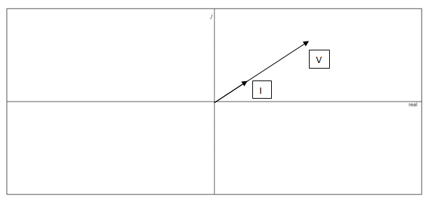
Fig. 15.82
Expert Solution & Answer
Want to see the full answer?
Check out a sample textbook solution
Students have asked these similar questions
Impedance of AC circuit and Admittance of AC circuitSHOW THE CIRCUIT USING ANY SOFTWARE OR YOU CAN DRAW IT MANUAALYY thNAKSS
Determine the capacitance value if the capacitive
reactance of 15 Kohms operates on a 40 Hz
supply.
a. 2.652 micro farad
O b. 26.52 micro farad
O c. 0.2652 MF
d. 0.2652 micro farad
An inductive reactance of 6 ohm is connected in series with a parallel combination of a variable resistor R and a capacitive reactance of 15 ohm across 100V , 50 hz supply.
a. Solve for the frequency so that the magnitude of the inductive reactance is 2 times the magnitude of capacitive reactance.
b. Solve for the value of R so that the total current I will be maximum.
Chapter 15 Solutions
Laboratory Manual for Introductory Circuit Analysis
Ch. 15 - For the resistive element in Fig. 15.81: Write the...Ch. 15 - For the resistive element in Fig. 15.82: Write the...Ch. 15 - For the inductive element of Fig. 15.83: a. Write...Ch. 15 - For the inductive element of Fig. 15.84: Calculate...Ch. 15 - For the inductive element of Fig. 15.85: Write the...Ch. 15 - For the capacitive element of Fig. 15.86: Write...Ch. 15 - For the capacitive element of Fig. 15.87:...Ch. 15 - For the capacitive element of Fig. 15.88: Write...Ch. 15 - Sketch the impedance diagram of a 120 k resistor.Ch. 15 - Sketch the impedance diagram of a 5 mH coil...
Ch. 15 - Sketch the impedance diagram of a 0.02 F capacitor...Ch. 15 - Calculate the total impedance of the circuits in...Ch. 15 - Calculate the total impedance of the circuits in...Ch. 15 - Find the type and impedance in ohms of the series...Ch. 15 - For the circuit in Fig. 15.92 Find the total...Ch. 15 - Repeat problem 15 for the circuit in Fig. 15.93,...Ch. 15 - For the circuit in Fig. 15.94: Find the total...Ch. 15 - Repeat Problem 17 for the circuit in Fig. 15.95...Ch. 15 - For the circuit of Fig. 15.96: Find the total...Ch. 15 - For the circuit of Fig. 15.97: Find the current...Ch. 15 - Prob. 21PCh. 15 - Using the oscilloscope reading in Fig. 15.99,...Ch. 15 - Using the DMM current reading and the oscilloscope...Ch. 15 - Using the oscilloscope reading in Fig. 15.101:...Ch. 15 - An electrical load has a power factor of 0.8...Ch. 15 - Find the series element or elements that must be...Ch. 15 - Calculate the voltages V1andV2 for the circuits in...Ch. 15 - Calculate the voltages V1andV2 for the circuits in...Ch. 15 - For the circuit in Fig. 15.105: Determine...Ch. 15 - For the circuit in Fig. 15.106: a. Plot ZT and T...Ch. 15 - Prob. 31PCh. 15 - For the series R-L-C circuit in Fig. 15.108: Plot...Ch. 15 - For the series R-C circuit in Fig. 15.109:...Ch. 15 - For the circuit in Fig. 15.110, determine the...Ch. 15 - For the oscilloscope traces in Fig. 15.111:...Ch. 15 - For the network in Fig. 15.92 (usef=1kHz):...Ch. 15 - For the network in Fig. 15.93: Plot the impedance...Ch. 15 - For the network in Fig. 15.105: Find the rms...
Additional Engineering Textbook Solutions
Find more solutions based on key concepts
Identify the type of input and output configuration for each diff-amp in Figure 18-35.
Electronics Fundamentals: Circuits, Devices & Applications
What is the color code for a 365- five-band precision resistor with a tolerance of 5 percent?
ELECTRICITY FOR TRADES (LOOSELEAF)
How many coulombs do 93.8 1016 electrons represent?
Principles Of Electric Circuits
The voltage source of the circuit shown in Fig. P1.29 is given by s(t)=25cos(4104t45)(V). Obtain an expression ...
Fundamentals of Applied Electromagnetics (7th Edition)
Analog Voltmeter Design Figure P2-98(a) shows a voltmeter circuit consisting of a D'Arsonval meter, two series ...
ANALYSIS+DESIGN OF LINEAR CIRCUITS(LL)
Does the severity of an electric shock increase ordecrease with eh of the following changes? a. A decrease in t...
Electric Motors and Control Systems
Knowledge Booster


Learn more about
Need a deep-dive on the concept behind this application? Look no further. Learn more about this topic, electrical-engineering and related others by exploring similar questions and additional content below.Similar questions
- Convert the following instantaneous currents to phasors, using cos(t) as the reference. Give your answers in both rectangular and polar form. (a) i(t)=5002cos(t30) (b) i(t)=4sin(t+30) (c) i(t)=5cos(t15)+42sin(t+30)arrow_forwardIf A = 20260° and B= 5230°, find the products AB and BB".arrow_forwardSolve for the current in this circuit. Give its phase angle and write it as a phasor. V1 20 V 1 kHz L1 10 ohmsarrow_forward
- 1. Consider the two circuits below being driven by an AC source Vac. What is the impedance between terminals a and b as the frequency goes to zero? What is the impedance as the frequency become extremely high? ell L1 1 ΜΗ C1 1 µF C2 1 µF b t Vac sine L2 1 ΜΗ C3 1 µF L3 1 µH Vac sinearrow_forwardWhat is the reactance of 3.00 microfarad capacitor? What is the impedance of the capacitor in series of 300 ohms?arrow_forwardIf an electrical circuit draws 100W + J100VAR from a sinusoidal source, then what would the circuit be? Explain why. a) a pure resistor circuit b) a series or parallel R-L circuit c) a series or parallel R-C circuit d) a series L-C circuitarrow_forward
- Consider the circuit shown in Figure 2.23 in time domain. Convert the entire circuit into phasor domain.arrow_forward1:45 Capture1.PNG * Q/ Find the active and reactive power for below circuit, the frequency = 50 Hz for all circuit? 100 10 16HF 100 V 1 mHarrow_forwardneed in 1 hour pls thanks 1. EXPRESS (j-3)¹⁹ IN RECTANGULAR FORM.arrow_forward
- The phase angle difference between the voltage and current in an AC circuit is 0. Which of the following is true? A The current lags the voltage by 0. B The angle between resistance and reactance is e. The angle between resistance and impedance is e. The current leads the voltage by 0.arrow_forwardCircuits 1 HW 3 Q9arrow_forwardPHASE DIFFERENCE FIND( NEED NEAT HANDWRITTEN SOLUTION ONLY OTHERWISE DOWNVOTE).arrow_forward
arrow_back_ios
SEE MORE QUESTIONS
arrow_forward_ios
Recommended textbooks for you
 Power System Analysis and Design (MindTap Course ...Electrical EngineeringISBN:9781305632134Author:J. Duncan Glover, Thomas Overbye, Mulukutla S. SarmaPublisher:Cengage Learning
Power System Analysis and Design (MindTap Course ...
Electrical Engineering
ISBN:9781305632134
Author:J. Duncan Glover, Thomas Overbye, Mulukutla S. Sarma
Publisher:Cengage Learning
02 - Sinusoidal AC Voltage Sources in Circuits, Part 1; Author: Math and Science;https://www.youtube.com/watch?v=8zMiIHVMfaw;License: Standard Youtube License