
Concept explainers
(a)
The value of the collector current, base current and the node voltages for the given values.
(a)
Answer to Problem 17.38P
The value of the base voltage
Explanation of Solution
Calculation:
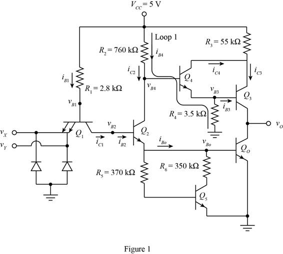
The given diagram is shown in Figure 1
The expression for the voltage
Substitute
The expression for the base current of the first transistor is given by,
Substitute
The expression for the voltage
Substitute
The first transistor are forward biased and the other transistor are operating in the cut off region therefore the value of the different collector current is given by,
The expression for the current
The conversion from
The conversion from
The expression for the value of the current
Substitute
The expression for the value of the current
Substitute
The expression for the base voltage of the fourth transistor is given by,
Substitute
Conclusion:
Therefore, the value of the base voltage
(b)
The value of the collector current, base current and the node voltages for the given value.
(b)
Answer to Problem 17.38P
The value of the base voltage
Explanation of Solution
Calculation:
The expression for the value of voltage
Substitute
The expression for the base current of the first transistor is given by,
Substitute
The expression for the voltage
Substitute
The expression for the value of the second transistor is given by,
Substitute
The expression for the value of the current
Substitute
The expression for the voltage
Substitute
The expression for the value of the current
Substitute
The expression for the value of the voltage
The expression for the value of the current
The expression for the value of the current
The expression for the value of the voltage
Substitute
The expression for the value of the current
Substitute
The expression for the value of the current
Substitute
Conclusion:
Therefore, the value of the base voltage
Want to see more full solutions like this?
Chapter 17 Solutions
Microelectronics: Circuit Analysis and Design


- Discuss the main limitations of the FSK modulation circuitarrow_forwardExplain with the aid of equations the following: How to improve the SNqR in the PCM system?arrow_forwardWhat is the best-case rising delay a standard size three-input NAND gate that does not have an external load, written in terms of RC (numerical result only)?arrow_forward
- Sketch the Bipolar RZ Voltage encoding on a classic Ethernet for the bit stream0001110101.arrow_forwardIn the figure below, an x(t) signal varying between +- 1.6 V is split into 8 quanta levels and converted to a digital signal. being converted. a) Calculate the quantization gap voltage (step)? b) Draw the PAM, PCM and ASK outputs in this conversion process? c) Calculate bit transmission rate if sampling pulse frequency ?? = 2kHz.arrow_forwardExplain with the aid of equations the following: i. How to improve the noiseless channel capacity? ii. How to improve the SNqR in the PCM system?arrow_forward
- Draw and show the BFSK modulation waveform for the given binary data sequence “1,0,0,1”, and also draw its BFSK constellation diagram.arrow_forward3. Which of the following is a key characteristic of orthogonal frequency-division multiplexing?A. Amplitude modulationB. Noise performanceC. Digital modulationD. Spectral efficiencyarrow_forwardEstimate iB and iC of the Schottky transistor shown if the external collector terminal isopen. Assume the forward voltage of the Schottkydiode is 0.45 V.arrow_forward
 Introductory Circuit Analysis (13th Edition)Electrical EngineeringISBN:9780133923605Author:Robert L. BoylestadPublisher:PEARSON
 Delmar's Standard Textbook Of ElectricityElectrical EngineeringISBN:9781337900348Author:Stephen L. HermanPublisher:Cengage Learning
 Programmable Logic ControllersElectrical EngineeringISBN:9780073373843Author:Frank D. PetruzellaPublisher:McGraw-Hill Education
 Fundamentals of Electric CircuitsElectrical EngineeringISBN:9780078028229Author:Charles K Alexander, Matthew SadikuPublisher:McGraw-Hill Education
 Electric Circuits. (11th Edition)Electrical EngineeringISBN:9780134746968Author:James W. Nilsson, Susan RiedelPublisher:PEARSON
 Engineering ElectromagneticsElectrical EngineeringISBN:9780078028151Author:Hayt, William H. (william Hart), Jr, BUCK, John A.Publisher:Mcgraw-hill Education,