
Videos
The transistor in the circuit in Figure P3.27 has parameters
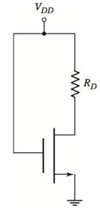
Figure P3.27
(a)
To sketch: A load line and labelQ -point.
To find: The region of operation of transistor.
Answer to Problem 3.27P
A load line along with Q -point is shown in Figure 1.
The transistor operates in triode region.
Explanation of Solution
Given Information:
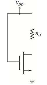
The given circuit is shown below.
Calculation:
The value of
The value of
Applying Kirchhoff’s voltage in drain-source terminal:
Assuming the Mosfet operates in triode region:
The expression of drain current in triode region:
From equation (1):
From above calculations:
Hence, the assumption is correct and the transistor is biased in triode region.
The value of Q -point is:
The diagram of load line is sketched as follows:
From equation (1):
It is equation of straight line with negative slope.
At
At
Figure 1
(b)
To sketch: A load line and labelQ -point.
To find: The region of operation of transistor.
Answer to Problem 3.27P
A load-line along with Q -point is shown in Figure 2.
The transistor operates in triode region.
Explanation of Solution
Given Information:
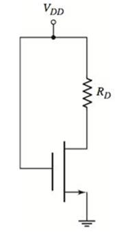
The given circuit is shown below.
Calculation:
The value of
The value of
Applying Kirchhoff’s voltage in drain-source terminal:
Assuming the Mosfet operates in triode region:
The expression of drain current in triode region:
From equation (2):
From above calculations:
Hence, the assumption is correct and the transistor is biased in triode region.
The value of Q-point is:
The diagram of load line is sketched as follows:
From equation (1):
It is equation of straight line with negative slope.
At
At
Figure 2
Want to see more full solutions like this?
Chapter 3 Solutions
Microelectronics: Circuit Analysis and Design


- 3.For the Silicon transistors of the circuit of figure 3, β = 110 and the Early Voltage is equal to infinity a) Determine the value of the gain Av = vo/vs2Note: It is known that Vcc = 25v.arrow_forwardA bipolar NPN transistor has a DC Beta of 200mA. Calculate the base current IB required to switch a resistive (collector) load of 5000µA Please show solution Choices: 20µA0.25mA0.025mA250µAarrow_forwardQ3:Choose One of the following: : (A)In common emmiter voltage divider bias of BJT, Vcc = 25V; R1= 10 k ohm; R2, = 2.2 k ohm ;Rc = 3.6 k ohm and RE = 1 k ohm.Determain Vec at ß = 120.using Exact analysis Draw the equvelent circuit inaddition the DC load line curve . (B)For self bais(Emitter resistace bais) of BJT,Vcc= 22 V, lb = 45macroA, a = 0.99, RE = 1 k ohm. Determain VCe Draw the equvelent circuit inaddition to DC load line curve.arrow_forward
- 1. Use the figure below to solve following questions (a) Solve the following dc quantitiesi. VB(Q1)ii. VE(Q1)iii. IE(Q1)iv. VC(Q1)v. VB(Q2)vi. VE(Q2)vii. IE(Q2)viii. VC(Q2)(b) Suppose that the emitter follower is omitted and the output from thecollector of Q1 is capacitively coupled to the 250Ω load, RL. What isthe output voltage across the 250Ω load?arrow_forwardQ3) Bring out the advantages and disadvantages of microwave tube devices and semiconductor devices. What are the most common types of microwave diodes and transistors in use give their basic features and applications? What are the most common types of microwave ICs? Give details of the circuit elements and applicationsarrow_forwarda- In the circuit shown in Figure VCC = 13.6 V, görülen = 145and since the transistor is of silicon type,Required for IC = 5 mA when VCE = 6.8 VCalculate the RC and RB values. Calculate the power consumed by the transistor.b- RE = 1.2K to the emitter end of the transistorIf connected, calculate VCE, IC, IB currents.Interpret the final state of the circuit.arrow_forward
- For the circuit shown in Fig. 3, determine the values of R1 and R2 that make that id = 3.6 m, if both transistors have k = 0.4 mili-ampers by volts to square, and vt = 0.5 volts. (It is known that the DC source delivers 4 mA.)arrow_forwardHey, can you please make sure this question is solved correctly and step by step solution to the way to approach and how it's done please. I want to learn how to do this type of problem. Fig. 3 is a simplified structure of the MOSFET (NMOS) transistor.What are the requirements for MOSFET to operate in:a) triode mode?b) saturation mode?c) cutoff mode?Explainarrow_forwardShow that the drain current IDQ is approximately equal to 3.65 mA (graphically or otherwise). Then calculate VDSQ.arrow_forward
- 1. A circuit with 2 or more connected transistors is called _________ or multi-staged amplification. A) Cascaded B) Inverter C) Dual amplifier D) Rectifier2. He is an Austrian-Hungarian physicist who developed the first undocumented semi-conductor device. A) Edward Howard B) Elizabeth Miles C) Morgan Sparks D) Julies Edgar Lilienfeld3. Who made the Bipolar junction? A) Daniel Levi B) John Jonson C) Mathew Wills D) Morgan Sparksarrow_forwardConsider the circuitshown below, where K = 0.2 mA/V2 and Vto = 0.8V.1) If V1 = 3V, what is the maximum V3 that can be used while M1 remains insaturation?2) Suppose V1 and V3 must be equal. What is the maximum value that theycan have while M1 remains in saturation?arrow_forwardFor an NPN Bipolar Junction Transistor base-emitter voltage, VBE is 0.7 V at collector current,Ic of 1mA. Calculate the saturation current, emitter-base voltage, emitter current whencollector current is (X+2) mA. Assume β =100 and T=300 K for your calculation.arrow_forward
 Introductory Circuit Analysis (13th Edition)Electrical EngineeringISBN:9780133923605Author:Robert L. BoylestadPublisher:PEARSON
 Delmar's Standard Textbook Of ElectricityElectrical EngineeringISBN:9781337900348Author:Stephen L. HermanPublisher:Cengage Learning
 Programmable Logic ControllersElectrical EngineeringISBN:9780073373843Author:Frank D. PetruzellaPublisher:McGraw-Hill Education
 Fundamentals of Electric CircuitsElectrical EngineeringISBN:9780078028229Author:Charles K Alexander, Matthew SadikuPublisher:McGraw-Hill Education
 Electric Circuits. (11th Edition)Electrical EngineeringISBN:9780134746968Author:James W. Nilsson, Susan RiedelPublisher:PEARSON
 Engineering ElectromagneticsElectrical EngineeringISBN:9780078028151Author:Hayt, William H. (william Hart), Jr, BUCK, John A.Publisher:Mcgraw-hill Education,