
Machine Elements in Mechanical Design (6th Edition) (What's New in Trades & Technology)
6th Edition
ISBN: 9780134441184
Author: Robert L. Mott, Edward M. Vavrek, Jyhwen Wang
Publisher: PEARSON
expand_more
expand_more
format_list_bulleted
Videos
Textbook Question
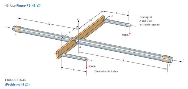
Chapter 3, Problem 49P
For Problems 48−50, draw the free-body diagram of the main shaft portion, labeled A, B, and C. Include any unbalanced torque on the shaft that tends to rotate it about the z-axis. In each case, the reaction to the unbalanced torque is taken at the right end of the shaft labeled C. Then draw the complete shearing force and bending moment diagrams for loading in the y−z plane. Also prepare a graph of the torque in the shaft as a function of position along the shaft from A to C.
Expert Solution & Answer
Want to see the full answer?
Check out a sample textbook solution
Students have asked these similar questions
Thank you so much in advance!!
A Solid circular shaft with a 120 mm diameter and a number of pulleys loaded as shown. The end A is fixed. Calculate the (a) Torque at A. (b) the Maximum shear stress in the shaft and (c) the Angle of twist at A, B, C and D. (Note: The shear modulus of the material is 27 GPa)
A flange bolt coupling consists of eight 0.375” diameter bolt on a bolt circle 11” diameter, and five ¾” diameter bolts on a concentric circle of 5” diameter. Calculate the torque can be applied without exceeding a shearing stress of 7000 psi in the bolts.
The shaft shown in the figure is machined from AISI 1040 CD steel. The shaft rotates at 1600 rpm and is supported in rolling bearings at A and B. The applied forces are F1 = 1600 lbf and F2 = 640 lbf. A steady torque of 1600 lbf·in is being transmitted through the shaft between the points of application of the forces.
Chapter 3 Solutions
Machine Elements in Mechanical Design (6th Edition) (What's New in Trades & Technology)
Ch. 3 - A tensile member in a machine structure is...Ch. 3 - Compute the stress in a round bar having a...Ch. 3 - Compute the stress in a rectangular bar having...Ch. 3 - A link in a packaging machine mechanism has a...Ch. 3 - Two circular rods support the 3800 lb weight of a...Ch. 3 - A tensile load of 5.00 kN is applied to a square...Ch. 3 - An aluminum rod is made in the form of a hollow...Ch. 3 - Compute the stress in the middle portion of rod AC...Ch. 3 - Compute the forces in the two angled rods in...Ch. 3 - If the rods from Problem 9 are circular, determine...
Ch. 3 - Repeat Problems 9 and 10 if the angle is 15 .Ch. 3 - Figure P312 shows a small truss spanning between...Ch. 3 - The truss shown in Figure P313 spans a total space...Ch. 3 - Figure P314 shows a short leg for a machine that...Ch. 3 - Consider the short compression member shown in...Ch. 3 - Refer Figure P38 . Each of the pins at A, B, and C...Ch. 3 - Compute the shear stress in the pins connecting...Ch. 3 - Prob. 18PCh. 3 - Prob. 19PCh. 3 - Prob. 20PCh. 3 - Prob. 21PCh. 3 - Compute the torsional shear stress in a circular...Ch. 3 - If the shaft of Problem 22 is 850 mm long and is...Ch. 3 - Compute the torsional shear stress due to a torque...Ch. 3 - Compute the torsional shear stress in a solid...Ch. 3 - Compute the torsional shear stress in a hollow...Ch. 3 - Compute the angle of twist for the hollow shaft of...Ch. 3 - A square steel bar, 25 mm on a side and 650 mm...Ch. 3 - A 3.00 in-diameter steel bar has a flat milled on...Ch. 3 - A commercial steel supplier lists rectangular...Ch. 3 - A beam is simply supported and carries the load...Ch. 3 - For each beam of Problem 31, compute its weight if...Ch. 3 - For each beam of Problem 31, compute the maximum...Ch. 3 - For the beam loading of Figure P334, draw the...Ch. 3 - For the beam loading of Figure P334, design the...Ch. 3 - Figure P336 shows a beam made from 4 in schedule...Ch. 3 - Select an aluminum I-beam shape to carry the load...Ch. 3 - Figure P338 represents a wood joist for a...Ch. 3 - For Problems 39 through 50, draw the free-body...Ch. 3 - Prob. 40PCh. 3 - For Problems 39 through 50, draw the free-body...Ch. 3 - Prob. 42PCh. 3 - Prob. 43PCh. 3 - Prob. 44PCh. 3 - For Problems 39 through 50, draw the free-body...Ch. 3 - For Problems 39 through 50, draw the free-body...Ch. 3 - For Problems 39 through 50, draw the free-body...Ch. 3 - For Problems 4850, draw the free-body diagram of...Ch. 3 - For Problems 4850, draw the free-body diagram of...Ch. 3 - Prob. 50PCh. 3 - Compute the maximum tensile stress in the bracket...Ch. 3 - Compute the maximum tensile and compressive...Ch. 3 - For the lever shown in Figure P353 (a), compute...Ch. 3 - Compute the maximum tensile stress at sections A...Ch. 3 - Prob. 55PCh. 3 - Refer to Figure P38. Compute the maximum tensile...Ch. 3 - Prob. 57PCh. 3 - Refer to P342. Compute the maximum stress in the...Ch. 3 - Refer to P343. Compute the maximum stress in the...Ch. 3 - Prob. 60PCh. 3 - Figure P361 shows a valve stem from an engine...Ch. 3 - The conveyor fixture shown in Figure P362 carries...Ch. 3 - For the flat plate in tension in Figure P363,...Ch. 3 - For Problems 64 through 68, compute the maximum...Ch. 3 - For Problems 64 through 68, compute the maximum...Ch. 3 - For Problems 64 through 68, compute the maximum...Ch. 3 - For Problems 64 through 68, compute the maximum...Ch. 3 - Prob. 68PCh. 3 - Figure P369 shows a horizontal beam supported by a...Ch. 3 - Prob. 70PCh. 3 - Prob. 71PCh. 3 - The beam shown in Figure P372 is a stepped, flat...Ch. 3 - Figure P373 shows a stepped, flat bar having a...Ch. 3 - Figure P374 shows a bracket carrying opposing...Ch. 3 - Prob. 75PCh. 3 - Figure P376 shows a lever made from a rectangular...Ch. 3 - For the lever in P376, determine the maximum...Ch. 3 - Figure P378 shows a shaft that is loaded only in...Ch. 3 - Prob. 79PCh. 3 - Prob. 80PCh. 3 - A hanger is made from ASTM A36 structural steel...Ch. 3 - A coping saw frame shown in Figure P382 is made...Ch. 3 - Prob. 83PCh. 3 - Figure P384 shows a hand garden tool used to break...Ch. 3 - Figure P385 shows a basketball backboard and goal...Ch. 3 - Prob. 86P
Knowledge Booster


Learn more about
Need a deep-dive on the concept behind this application? Look no further. Learn more about this topic, mechanical-engineering and related others by exploring similar questions and additional content below.Similar questions
- Repeat Problem 11.2-3 assuming that R= 10 kN · m/rad and L = 2 m.arrow_forwardThe shaft is fixed at ends A and B and has a positive torque T a distance of 4m from A and 8m from end B. If the angle of twist is zero and the reaction torque at A is 334N-m, what is the magnitute of applied torque T?arrow_forwardA circular shaft with 50mm and its lenght is 850mm long and is made of steel, the shaft is subjected to a torque of 800Nm. Compute the angle of twist of one end in relation to the other.arrow_forward
- Two designs for a shaft are being considered. Both have an outside diameter of 50 mm and are 600 mm long. Oneis solid but the other is hollow with an inside diameter of 40 mm. Both are made from steel. Compare the torsionalshear stress, the angle of twist, and the mass of the two designs if they are subjected to a torque of 850 N ·m.arrow_forwardWhat is the minimum diameter of a solid steel shaft that will not twist through more than 3 in a 6 m length when subjected to a torque of 12 kN-m? (b) what maximum stress is developed in the shaft? Use G-83 GPa. Remember the angle of twist (0) calculated using the equations is in radians. Incorrect solution will be downvotedarrow_forwardTopic: FUNDAMENTAL CONCEPT OF STRAIN (statically indeterminate) and TORSION (circular shafts and thin-walled tubes). Problem: A shaft with a constant diameter of 2” is loaded by torques applied to gears attached to it as shown. Using G = 12 x 106 psi, determine the relative angle of twist (in degree) of gear A relative to gear D. Use 2 decimal places. Use the given sign convention for uniformity. Provide a torque diagramarrow_forward
- A flange bolt coupling consists of six ½” diameter bolt spaced evenly around a bolt circle of 14” diameter. Calculate the torque capacity of the coupling if the allowable shearing stress in the bolts is 5000 psi.arrow_forwardThe composite shaft below, consists of three sections, a tubular indication welded, through flanges Aand B, two 1” diameter bars. Neglect the thickness of the flanges and determine the angle of twist of the endC from shaft to end D. Shaft 0 is relative to a torque of lb × ft. The A-36 material.arrow_forwardaccording to Maximum Shear Stress theory ,Calculate the factor of safety of the shaft When it is subjected to an end thrust producing stress of 90 MPa and the maximum shearing stress on the surface arising from torsion is 60 MPa.The yield point of the material in simple tension was found to be 300 MPa.arrow_forward
- The figure shows a shaft carrying three gears that rotates at 1150 rpm. Gear A delivers power =10kw to a mating gear that drives a mixer. Gear C delivers power =15kw to a different mating gear that drives a circular saw. All power comes into the shaft through gear B. Draw sheardiagramand bending moment diagram. Considering only torsion, compute the body free diagram and shearing stress in each part of the shaft. Consider stress concentrations, assume the Material is 1144 OQT 1300.arrow_forwardA belted transmission system is loaded as shown in Figure. The input shaft takes its power from a 40 kW motor that runs at 1000 rpm. The output shaft drives a certain machinery equipment. Determine the following: a. torque available at each of shafts A, B, and C. b. torsional stress induced on the 60 mm diameter output shaft c. length of belt required to connect each pair of pulleys d. maximum bending moment on shaft B, considering a belt coefficient of friction of 0.30.arrow_forwardA solid constant-diameter circular shaft is subjected to the torques of TA = 560 lb·ft, TB = 1080 lb·ft, TC = 850 lb·ft, and TD = 330 lb·ft, acting in the directions shown. The bearings shown allow the shaft to turn freely.(a) Plot a torque diagram showing the internal torque in segments (1), (2), and (3) of the shaft. Use the sign convention presented in Section 6.6.(b) If the allowable shear stress in the shaft is 4200 psi, what is the minimum acceptable diameter for the shaft?arrow_forward
arrow_back_ios
SEE MORE QUESTIONS
arrow_forward_ios
Recommended textbooks for you
 Mechanics of Materials (MindTap Course List)Mechanical EngineeringISBN:9781337093347Author:Barry J. Goodno, James M. GerePublisher:Cengage Learning
Mechanics of Materials (MindTap Course List)
Mechanical Engineering
ISBN:9781337093347
Author:Barry J. Goodno, James M. Gere
Publisher:Cengage Learning
Everything About TRANSVERSE SHEAR in 10 Minutes!! - Mechanics of Materials; Author: Less Boring Lectures;https://www.youtube.com/watch?v=4x0E9yvzfCM;License: Standard Youtube License