
Machine Elements in Mechanical Design (6th Edition) (What's New in Trades & Technology)
6th Edition
ISBN: 9780134441184
Author: Robert L. Mott, Edward M. Vavrek, Jyhwen Wang
Publisher: PEARSON
expand_more
expand_more
format_list_bulleted
Concept explainers
Videos
Textbook Question
Chapter 3, Problem 78P
Figure P3−78 shows a shaft that is loaded only in bending. Bearings are located at points B and D to allow the shaft to rotate. Pulleys at A, C, and E carry cables that support loads from below while allowing the shaft to rotate. Compute the maximum stress due to bending in the shaft considering stress concentrations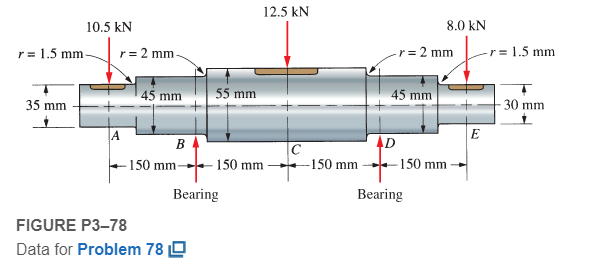
Expert Solution & Answer
Want to see the full answer?
Check out a sample textbook solution
Students have asked these similar questions
Q3 The figure shows a round shaft from a gear transmission. Gears are mounted at points A, C, and E. Supporting bearings are at B and D. The forces transmitted from the gears to the shaft are shown, all acting downward. Compute the maximum stress due to bending in the shaft, accounting for stress concentrations. calculate the safety factor for the material selected.if martial 4150 OQT 1300
force 1 (f1)=9.5 kn ,Force 2(f2)=13.5Kn ,Force3 (f3)=18Kn
Consider the case of shafts subjected to bending moment only.
Figure Q2 shows a pair of wheels of a railway wagon that carries a load of 50kN on each axle box, acting at a distance of 100 mm outside the wheel base. The gauge of the rails is 1.4m.
Figure Q2
If the stress is not to exceed 100MPa, find,
the diameter of the axle between the wheels, and
if a hollow circular shaft is to be used in place of the solid shaft, find the inside and outside diameter when the ratio of inside to outside diameter is 0.5.
Q3 The figure shows a round shaft from a gear transmission. Gears are mounted at points A, C, and E. Supporting bearings are at B and D The forces transmitted from the gears to the shaft are shown, all acting downward. Compute the maximum stress due to bending in the shaft, accounting for stress concentrations. calculate the safety factor for the material selected. if matrial 4150 Anneald ,if F1=9kn,F2=13kn,F3=15kn
Chapter 3 Solutions
Machine Elements in Mechanical Design (6th Edition) (What's New in Trades & Technology)
Ch. 3 - A tensile member in a machine structure is...Ch. 3 - Compute the stress in a round bar having a...Ch. 3 - Compute the stress in a rectangular bar having...Ch. 3 - A link in a packaging machine mechanism has a...Ch. 3 - Two circular rods support the 3800 lb weight of a...Ch. 3 - A tensile load of 5.00 kN is applied to a square...Ch. 3 - An aluminum rod is made in the form of a hollow...Ch. 3 - Compute the stress in the middle portion of rod AC...Ch. 3 - Compute the forces in the two angled rods in...Ch. 3 - If the rods from Problem 9 are circular, determine...
Ch. 3 - Repeat Problems 9 and 10 if the angle is 15 .Ch. 3 - Figure P312 shows a small truss spanning between...Ch. 3 - The truss shown in Figure P313 spans a total space...Ch. 3 - Figure P314 shows a short leg for a machine that...Ch. 3 - Consider the short compression member shown in...Ch. 3 - Refer Figure P38 . Each of the pins at A, B, and C...Ch. 3 - Compute the shear stress in the pins connecting...Ch. 3 - Prob. 18PCh. 3 - Prob. 19PCh. 3 - Prob. 20PCh. 3 - Prob. 21PCh. 3 - Compute the torsional shear stress in a circular...Ch. 3 - If the shaft of Problem 22 is 850 mm long and is...Ch. 3 - Compute the torsional shear stress due to a torque...Ch. 3 - Compute the torsional shear stress in a solid...Ch. 3 - Compute the torsional shear stress in a hollow...Ch. 3 - Compute the angle of twist for the hollow shaft of...Ch. 3 - A square steel bar, 25 mm on a side and 650 mm...Ch. 3 - A 3.00 in-diameter steel bar has a flat milled on...Ch. 3 - A commercial steel supplier lists rectangular...Ch. 3 - A beam is simply supported and carries the load...Ch. 3 - For each beam of Problem 31, compute its weight if...Ch. 3 - For each beam of Problem 31, compute the maximum...Ch. 3 - For the beam loading of Figure P334, draw the...Ch. 3 - For the beam loading of Figure P334, design the...Ch. 3 - Figure P336 shows a beam made from 4 in schedule...Ch. 3 - Select an aluminum I-beam shape to carry the load...Ch. 3 - Figure P338 represents a wood joist for a...Ch. 3 - For Problems 39 through 50, draw the free-body...Ch. 3 - Prob. 40PCh. 3 - For Problems 39 through 50, draw the free-body...Ch. 3 - Prob. 42PCh. 3 - Prob. 43PCh. 3 - Prob. 44PCh. 3 - For Problems 39 through 50, draw the free-body...Ch. 3 - For Problems 39 through 50, draw the free-body...Ch. 3 - For Problems 39 through 50, draw the free-body...Ch. 3 - For Problems 4850, draw the free-body diagram of...Ch. 3 - For Problems 4850, draw the free-body diagram of...Ch. 3 - Prob. 50PCh. 3 - Compute the maximum tensile stress in the bracket...Ch. 3 - Compute the maximum tensile and compressive...Ch. 3 - For the lever shown in Figure P353 (a), compute...Ch. 3 - Compute the maximum tensile stress at sections A...Ch. 3 - Prob. 55PCh. 3 - Refer to Figure P38. Compute the maximum tensile...Ch. 3 - Prob. 57PCh. 3 - Refer to P342. Compute the maximum stress in the...Ch. 3 - Refer to P343. Compute the maximum stress in the...Ch. 3 - Prob. 60PCh. 3 - Figure P361 shows a valve stem from an engine...Ch. 3 - The conveyor fixture shown in Figure P362 carries...Ch. 3 - For the flat plate in tension in Figure P363,...Ch. 3 - For Problems 64 through 68, compute the maximum...Ch. 3 - For Problems 64 through 68, compute the maximum...Ch. 3 - For Problems 64 through 68, compute the maximum...Ch. 3 - For Problems 64 through 68, compute the maximum...Ch. 3 - Prob. 68PCh. 3 - Figure P369 shows a horizontal beam supported by a...Ch. 3 - Prob. 70PCh. 3 - Prob. 71PCh. 3 - The beam shown in Figure P372 is a stepped, flat...Ch. 3 - Figure P373 shows a stepped, flat bar having a...Ch. 3 - Figure P374 shows a bracket carrying opposing...Ch. 3 - Prob. 75PCh. 3 - Figure P376 shows a lever made from a rectangular...Ch. 3 - For the lever in P376, determine the maximum...Ch. 3 - Figure P378 shows a shaft that is loaded only in...Ch. 3 - Prob. 79PCh. 3 - Prob. 80PCh. 3 - A hanger is made from ASTM A36 structural steel...Ch. 3 - A coping saw frame shown in Figure P382 is made...Ch. 3 - Prob. 83PCh. 3 - Figure P384 shows a hand garden tool used to break...Ch. 3 - Figure P385 shows a basketball backboard and goal...Ch. 3 - Prob. 86P
Knowledge Booster


Learn more about
Need a deep-dive on the concept behind this application? Look no further. Learn more about this topic, mechanical-engineering and related others by exploring similar questions and additional content below.Similar questions
- Repeat Problem 11.3-9. Use two C 150 × 12.2 steel shapes and assume that E = 205 GPa and L = 6 m.arrow_forwardCompare the angle of twist 1 for a thin-walled circular tube (see figure) calculated from the approximate theory for thin-walled bars with the angle of twist 2 calculated from the exact theory of torsion for circular bars, Express the ratio 12terms of the non-dimensional ratio ß = r/t. Calculate the ratio of angles of twist for ß = 5, 10, and 20. What conclusion about the accuracy of the approximate theory do you draw from these results?arrow_forwardA steel punch consists of two shafts: upper shaft and lower shaft. Assume that the upper shaft has a diameter d1= 24 mm and the bottom shaft has a diameter d2= 16 mm. The punch is used to insert a hole in a 4 mm plate, as shown in the figure. If a force P - 70 kN is required to create the hole, what is the average shear stress in the plate and the average compressive stress in the upper and lower shaft of the punch?arrow_forward
- A safety valve on the top of a tank containing steam under pressure p has a discharge hole of diameter d(see figure). The valve is designed to release the steam when the pressure reaches the value Pmax If the natural length of the spring, is L and its stiffness is k, what should be the dimension ft of the valve? (Express your result as a formula for h.)arrow_forwardFigure Q1 shows a solid steel shaft AF which is supported by frictionless bearings at B and F. It is coupled to an electric motor at A. The modulus of rigidity of steel shaft is 75 GPa. The shaft is loaded by the torque as stated in the figure below. Answer the following:(a) Calculate the maximum shear stress in the shaft. (b) Determine the total angle of twist between F and A. (c) If speed of the shaft is 50 rev/s, calculate the required power transmitted by the electric motor to the shaft.arrow_forwardA motor transmits 180 hp to the driving pulley, in the figure assuming that A takes 40 hp and C takes 140 hp, design the shaft for an allowable shear stress of 8000 lb/in2, the speed is 630 rpmarrow_forward
- the propeller on a ship shown in figure qi is subjected to a compressive axial force f of 180 kn as it pushes the water backward and a torsional load t of 15 kn.m as it turns through the water. the solid shaft has a diameter of 150 mm. it is made of c1018 steel with yield strength of 220 mpa, young's modulus of 200 gpa and poisson's ratio of 0.3. a) at the most critical material point of the shaft, calculate the stress state and sketch the corresponding stress element. b) what is the factor of safety of the shaft if it is designed according to:i) tresca criterion?ii) von mises criterion? c) by sketching the principal stresses on the tresca and von mises yield loci, briefly explain the reason for the difference in the factor of safety according to both criteria. d) without performing any calculation, would the factor of safety become higher, lower or the same according to tresca criterion if a hollow shaft with an inner diameter of 130 mm and an outer diameter of 150 mm of the same…arrow_forwardFigure Q1 shows a solid steel shaft AF which is supported by frictionless bearings at B and F. It is coupled to an electric motor at A. The modulus of rigidity of steel shaft is 75 GPa. The shaft is loaded by the torque as stated in the figure below. Answer the following:(a) Sketch the free body diagram and calculate the internal torque acting in each section of the shaft. (b) Calculate the maximum shear stress in the shaft. (c) Determine the total angle of twist between F and A.arrow_forwardProblem 4:Sketch the distribution of the shear stress due to torsion in a circular shaft. (simple sketch of shear stress “τ” vs. shaft radius “ρ” for the elastic region)arrow_forward
- The figure shows a round shaft from a gear transmission. Gears are mounted at points A, C, and E. Supporting bearings are at B and D. The forces transmitted from the gears to the shaft are shown, all acting downward. Compute the maximum stress due to bending in the shaft, accounting for stress concentrations. Draw shear diagram and moment diagram. calculate the safety factor for the material selected. The material is 4150 OQT 1300. Assume that f1 = 9.5 KN , f2= 13.5 KN and f3 =18 KNarrow_forwardFind factor of safety if the Ultimate Stress of a ductile material is 250.94 MPa. If the material is subjected to a loading condition that generates the working stress of 151.27 MPaarrow_forwardThe compound shaft shown in Fig. P-319 is attached to rigid supports. For the bronze segment AB, the diameter is 75 mm, τ ≤ 60 MPa, and G = 35 GPa. For the steel segment BC, the diameter is 50 mm, τ ≤ 80 MPa, and G = 83 GPa. If a = 2 m and b = 1.5 m, compute the maximum torque T that can be applied.arrow_forward
arrow_back_ios
SEE MORE QUESTIONS
arrow_forward_ios
Recommended textbooks for you
 Mechanics of Materials (MindTap Course List)Mechanical EngineeringISBN:9781337093347Author:Barry J. Goodno, James M. GerePublisher:Cengage Learning
Mechanics of Materials (MindTap Course List)
Mechanical Engineering
ISBN:9781337093347
Author:Barry J. Goodno, James M. Gere
Publisher:Cengage Learning
Solids: Lesson 53 - Slope and Deflection of Beams Intro; Author: Jeff Hanson;https://www.youtube.com/watch?v=I7lTq68JRmY;License: Standard YouTube License, CC-BY