
Machine Elements in Mechanical Design (6th Edition) (What's New in Trades & Technology)
6th Edition
ISBN: 9780134441184
Author: Robert L. Mott, Edward M. Vavrek, Jyhwen Wang
Publisher: PEARSON
expand_more
expand_more
format_list_bulleted
Concept explainers
Videos
Textbook Question
Chapter 3, Problem 84P
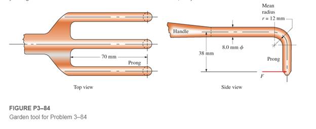
Figure P3−84 shows a hand garden tool used to break up soil. Compute the force applied to the end of one prong that would cause yielding in the curved area. The tool is made from cast aluminum, alloy 356.0-T6.
Expert Solution & Answer
Want to see the full answer?
Check out a sample textbook solution
Students have asked these similar questions
The figure below is a schematic drawing of a shaft that supports two V-belt pulleys. The loose belt tension on the pulley at A is 15% of the tension on the tight side. The shaft material has a yield strength of 300 MPa and an ultimate tensile strength of 520 MPa. Calculate the shaft diameter.
An input shaft of a gearbox with motor power P = 7 kW and rotation number n = 1300 rpm. The diameter of an input shaft is d = 20 mm and its material is 16MnCr5. A force of F = 2800 N forces the shaft due to the operation of a gear wheel connected with a wedge on the input shaft. The distances of the gear from the bearings are given as L₁ = 40 mm and L2 = 60 mm. In the most dangerous section, you are required to check the strength according to the S = 3 safety factor. If the section is unsafe in terms of strength, what changes would you make in the design to make it safe? (The surface of the spindle is machined as fine chips, reliability poor Kg = 1.).
For same problem setup in Q1 except for the length, if the yield strength is 145 MPa, calculate the critical length under which the column would fail by yield and over which the column would fail by buckling.
Chapter 3 Solutions
Machine Elements in Mechanical Design (6th Edition) (What's New in Trades & Technology)
Ch. 3 - A tensile member in a machine structure is...Ch. 3 - Compute the stress in a round bar having a...Ch. 3 - Compute the stress in a rectangular bar having...Ch. 3 - A link in a packaging machine mechanism has a...Ch. 3 - Two circular rods support the 3800 lb weight of a...Ch. 3 - A tensile load of 5.00 kN is applied to a square...Ch. 3 - An aluminum rod is made in the form of a hollow...Ch. 3 - Compute the stress in the middle portion of rod AC...Ch. 3 - Compute the forces in the two angled rods in...Ch. 3 - If the rods from Problem 9 are circular, determine...
Ch. 3 - Repeat Problems 9 and 10 if the angle is 15 .Ch. 3 - Figure P312 shows a small truss spanning between...Ch. 3 - The truss shown in Figure P313 spans a total space...Ch. 3 - Figure P314 shows a short leg for a machine that...Ch. 3 - Consider the short compression member shown in...Ch. 3 - Refer Figure P38 . Each of the pins at A, B, and C...Ch. 3 - Compute the shear stress in the pins connecting...Ch. 3 - Prob. 18PCh. 3 - Prob. 19PCh. 3 - Prob. 20PCh. 3 - Prob. 21PCh. 3 - Compute the torsional shear stress in a circular...Ch. 3 - If the shaft of Problem 22 is 850 mm long and is...Ch. 3 - Compute the torsional shear stress due to a torque...Ch. 3 - Compute the torsional shear stress in a solid...Ch. 3 - Compute the torsional shear stress in a hollow...Ch. 3 - Compute the angle of twist for the hollow shaft of...Ch. 3 - A square steel bar, 25 mm on a side and 650 mm...Ch. 3 - A 3.00 in-diameter steel bar has a flat milled on...Ch. 3 - A commercial steel supplier lists rectangular...Ch. 3 - A beam is simply supported and carries the load...Ch. 3 - For each beam of Problem 31, compute its weight if...Ch. 3 - For each beam of Problem 31, compute the maximum...Ch. 3 - For the beam loading of Figure P334, draw the...Ch. 3 - For the beam loading of Figure P334, design the...Ch. 3 - Figure P336 shows a beam made from 4 in schedule...Ch. 3 - Select an aluminum I-beam shape to carry the load...Ch. 3 - Figure P338 represents a wood joist for a...Ch. 3 - For Problems 39 through 50, draw the free-body...Ch. 3 - Prob. 40PCh. 3 - For Problems 39 through 50, draw the free-body...Ch. 3 - Prob. 42PCh. 3 - Prob. 43PCh. 3 - Prob. 44PCh. 3 - For Problems 39 through 50, draw the free-body...Ch. 3 - For Problems 39 through 50, draw the free-body...Ch. 3 - For Problems 39 through 50, draw the free-body...Ch. 3 - For Problems 4850, draw the free-body diagram of...Ch. 3 - For Problems 4850, draw the free-body diagram of...Ch. 3 - Prob. 50PCh. 3 - Compute the maximum tensile stress in the bracket...Ch. 3 - Compute the maximum tensile and compressive...Ch. 3 - For the lever shown in Figure P353 (a), compute...Ch. 3 - Compute the maximum tensile stress at sections A...Ch. 3 - Prob. 55PCh. 3 - Refer to Figure P38. Compute the maximum tensile...Ch. 3 - Prob. 57PCh. 3 - Refer to P342. Compute the maximum stress in the...Ch. 3 - Refer to P343. Compute the maximum stress in the...Ch. 3 - Prob. 60PCh. 3 - Figure P361 shows a valve stem from an engine...Ch. 3 - The conveyor fixture shown in Figure P362 carries...Ch. 3 - For the flat plate in tension in Figure P363,...Ch. 3 - For Problems 64 through 68, compute the maximum...Ch. 3 - For Problems 64 through 68, compute the maximum...Ch. 3 - For Problems 64 through 68, compute the maximum...Ch. 3 - For Problems 64 through 68, compute the maximum...Ch. 3 - Prob. 68PCh. 3 - Figure P369 shows a horizontal beam supported by a...Ch. 3 - Prob. 70PCh. 3 - Prob. 71PCh. 3 - The beam shown in Figure P372 is a stepped, flat...Ch. 3 - Figure P373 shows a stepped, flat bar having a...Ch. 3 - Figure P374 shows a bracket carrying opposing...Ch. 3 - Prob. 75PCh. 3 - Figure P376 shows a lever made from a rectangular...Ch. 3 - For the lever in P376, determine the maximum...Ch. 3 - Figure P378 shows a shaft that is loaded only in...Ch. 3 - Prob. 79PCh. 3 - Prob. 80PCh. 3 - A hanger is made from ASTM A36 structural steel...Ch. 3 - A coping saw frame shown in Figure P382 is made...Ch. 3 - Prob. 83PCh. 3 - Figure P384 shows a hand garden tool used to break...Ch. 3 - Figure P385 shows a basketball backboard and goal...Ch. 3 - Prob. 86P
Knowledge Booster


Learn more about
Need a deep-dive on the concept behind this application? Look no further. Learn more about this topic, mechanical-engineering and related others by exploring similar questions and additional content below.Similar questions
- In the figure shown, the cutaway view shows a solid aluminum alloy of L= 600mm, A= 707mm^2 and E= 70GPa rod within a closed-end bronze of L= 610mm, A= 1206mm^2 and E= 100GPa tube. Before the load P is applied, there is a clearance of 2mm between the rod flange at B and the tube closure at A. After load P is applied, the solid aluminum alloy rod stretches enough so that flange B contacts the closed end of the tube at A. If the load applied to the lower end of the aluminum rod is P= 345KN, calculate:A. The normal stress in bronze tube, in MPa.B. The elongation of bronze tube, in mm.arrow_forwardR1 and R2 reaction forces occur in the rolling bearings of the AB shaft, which is exposed to the F1 and F2 forces in the figure. Shaft surface is ground and Brinell Hardness of Shaft material is 376 MPa. Calculate the shaft life in the light of the given information.arrow_forwardA M20 × C4 bolt of mild steel is having yield stress of 320 MPa and factor of safety 3. The safe static tensile load in kN will bearrow_forward
- QUESTION 7 Figure 7 shows an assembly consist of circular shaft AB, solid circular BC and a circular CE. The shaft is made of titanium alloy steel and fixed at A. Segment AB is a hollow shaft, has an inner diameter of 25mm. While tube CE with the thickness 2mm has an outer diameter of 20mm. The assembly is subjected to torques of 1000 Nm at C, 210 m at D and 350 Nm at E. The alloy has modulus of rigidity, G = 44kN/mm^2 a) Draw the torque diagram of the shaft. b) Determine maximum shearing stress developed in each segment. c) Calculate the angle of twist at the right end of the shaft.arrow_forwardThe figure Q3 below shows a bolt holding together two components. The bolt has a loadbearing diameter of 6mm and a pitch of 1mm. It is made from steel with E=210 GPa. It istightened 5 degrees beyond normal contact. The hole it passes through is 8mm diameter andits clamping force is distributed to a diameter of 16mm.a) Determine an equation for the deflection of the bolt when in contact with component 1and component 2 as function of axial load? b) Write an equation for the deformation of component 1 in contact with both the bolt andcomponent 2 as a function of axial loading. c) Present an equation for the deflection of component 2 in contact with both component 1and the bolt as a function of axial loading.d) Establish a compatibility relationship for the deformation of structure in Fig. 3 e) Determine the force being exerted on component 1 and component 2arrow_forwardGiven: angle α=64o. Cross sections of both rods are square with sizes a1=21mm, a2=13mm. The rods are made of steel with yielding stress σY=270MPa; factor of safety n=2,2. Find: allowable value of force (in kN) from strength calculation FA = ?arrow_forward
- Question 4A close-coiled helical spring is to have a stiffness of 90 kN/m and is to exert a maximum force of 3.7 kN. If the mean diameter of the coils is 80 mm, and the maximum stress is not to exceed 300 MPa, calculate the required number of coils and the diameter of the steel rod from which the spring should be made (G=80 GPa).arrow_forwardTorsional moments affect the rods as shown in the figure. a- Draw the torque diagram on the rod. b- Draw the stress distributions on the bars on the sections. c- Determine whether the torsion moments applied to the rod can be safely carried by this rod. Note: - For steel: Tallowable: 120 MPa G= 83 GPa -For aluminum: Tallowable: 55 MPa G=28 GPa -Tip C is allowed to rotate no more than 4 degreesarrow_forwardThe figure gives the cross-section of a grade 25 cast-iron pressure vessel. A total of N bolts are to be used to resist a separating force of 150 kN. (a) Determine kb, km, and C. (b) Find the number of bolts required for a load factor of 2 where the bolts may be reused when the joint is taken apart. (c) With the number of bolts obtained in part (b), determine the realized load factor for overload, the yielding factor of safety, and the load factor for joint separation. Use (SI) units as it appliesarrow_forward
- A mild steel rod having a stress of 50 Mpa and having a diameter of 20 mm What is the force applied on it.arrow_forwardA component is subjected to a maximum cyclic stress of 750 MPa and a minimum of 70 MPa. The steelfrom which it is manufactured has an ultimate tensile strength, σu, of 1050 MPa and a measured endurancelimit, σe, of 400 MPa. The fully reversed stress at 1000 cycles is 750 MPa. Using both the Goodman and Gerbermean stress correction procedures, calculate the component life.arrow_forwardThe shaft of the crank lever is loaded by forces through a vertical pin and base plate as shown in Figure 1. The pin is subjected to a vertical force of 10 kN at C. An axial thrust of 20 kN , with the length of 200mm , is acting at D on the base plate which may be approximated as an equivalent axial force on the shaft AC and its other effect could be ignored. The shaft AC is supported at end A & B. The yield strength of the shaft material is taken as 250 MN/m2. (i)Evaluate the maximum principal stresses, minimum principal stresses and shear stress-induced in the shaft for the shaft diameter of 100 mm.arrow_forward
arrow_back_ios
SEE MORE QUESTIONS
arrow_forward_ios
Recommended textbooks for you
 Elements Of ElectromagneticsMechanical EngineeringISBN:9780190698614Author:Sadiku, Matthew N. O.Publisher:Oxford University Press
 Mechanics of Materials (10th Edition)Mechanical EngineeringISBN:9780134319650Author:Russell C. HibbelerPublisher:PEARSON
 Thermodynamics: An Engineering ApproachMechanical EngineeringISBN:9781259822674Author:Yunus A. Cengel Dr., Michael A. BolesPublisher:McGraw-Hill Education
 Control Systems EngineeringMechanical EngineeringISBN:9781118170519Author:Norman S. NisePublisher:WILEY
 Mechanics of Materials (MindTap Course List)Mechanical EngineeringISBN:9781337093347Author:Barry J. Goodno, James M. GerePublisher:Cengage Learning
 Engineering Mechanics: StaticsMechanical EngineeringISBN:9781118807330Author:James L. Meriam, L. G. Kraige, J. N. BoltonPublisher:WILEY
Elements Of Electromagnetics
Mechanical Engineering
ISBN:9780190698614
Author:Sadiku, Matthew N. O.
Publisher:Oxford University Press
Mechanics of Materials (10th Edition)
Mechanical Engineering
ISBN:9780134319650
Author:Russell C. Hibbeler
Publisher:PEARSON
Thermodynamics: An Engineering Approach
Mechanical Engineering
ISBN:9781259822674
Author:Yunus A. Cengel Dr., Michael A. Boles
Publisher:McGraw-Hill Education
Control Systems Engineering
Mechanical Engineering
ISBN:9781118170519
Author:Norman S. Nise
Publisher:WILEY
Mechanics of Materials (MindTap Course List)
Mechanical Engineering
ISBN:9781337093347
Author:Barry J. Goodno, James M. Gere
Publisher:Cengage Learning
Engineering Mechanics: Statics
Mechanical Engineering
ISBN:9781118807330
Author:James L. Meriam, L. G. Kraige, J. N. Bolton
Publisher:WILEY
EVERYTHING on Axial Loading Normal Stress in 10 MINUTES - Mechanics of Materials; Author: Less Boring Lectures;https://www.youtube.com/watch?v=jQ-fNqZWrNg;License: Standard YouTube License, CC-BY