
Machine Elements in Mechanical Design (6th Edition) (What's New in Trades & Technology)
6th Edition
ISBN: 9780134441184
Author: Robert L. Mott, Edward M. Vavrek, Jyhwen Wang
Publisher: PEARSON
expand_more
expand_more
format_list_bulleted
Concept explainers
Videos
Textbook Question
Chapter 3, Problem 13P
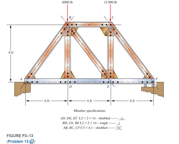
The truss shown in Figure P3−13 spans a total space of 18.0 ft and carries two concentrated loads on its top chord. The members are made from standard steel angle and channel shapes as indicated in the figure. Consider all joints to be pinned. Compute the stresses in all members near their midpoints away from the connections.
Expert Solution & Answer
Want to see the full answer?
Check out a sample textbook solution
Students have asked these similar questions
Compute the stresses at A and B on the link loaded as shown in Figure P-912 if P = 9000 lb and F = 3000 lb.
10.Find the stresses in member BC, BD and CF for the truss shown in Figure 8. Indicate tension or compression. The cross-sectional area of each member is 1600 mm2.
The figures below show a formed sheet-steel bracket. The total distributed load “W” on the bracket is 20 kN. It is secured to the support with two grade 5.8 bolts. The joint constant is C=0.183, and the bolts are preloaded to 70 percent of the proof load. The dimensions of the top flange are the same as the mounting flange.a) Find the external loads (P1 and P2) carried by upper and bottom bolts respectively if both resist the moment?b) Find the upper bolt diameter by ignoring direct shear load and determine/select a standard metric bolt size with a pitch for a design factor of 1,4.c) Is there any need to enlarge 5 mm dia. holes in the bracket?
Chapter 3 Solutions
Machine Elements in Mechanical Design (6th Edition) (What's New in Trades & Technology)
Ch. 3 - A tensile member in a machine structure is...Ch. 3 - Compute the stress in a round bar having a...Ch. 3 - Compute the stress in a rectangular bar having...Ch. 3 - A link in a packaging machine mechanism has a...Ch. 3 - Two circular rods support the 3800 lb weight of a...Ch. 3 - A tensile load of 5.00 kN is applied to a square...Ch. 3 - An aluminum rod is made in the form of a hollow...Ch. 3 - Compute the stress in the middle portion of rod AC...Ch. 3 - Compute the forces in the two angled rods in...Ch. 3 - If the rods from Problem 9 are circular, determine...
Ch. 3 - Repeat Problems 9 and 10 if the angle is 15 .Ch. 3 - Figure P312 shows a small truss spanning between...Ch. 3 - The truss shown in Figure P313 spans a total space...Ch. 3 - Figure P314 shows a short leg for a machine that...Ch. 3 - Consider the short compression member shown in...Ch. 3 - Refer Figure P38 . Each of the pins at A, B, and C...Ch. 3 - Compute the shear stress in the pins connecting...Ch. 3 - Prob. 18PCh. 3 - Prob. 19PCh. 3 - Prob. 20PCh. 3 - Prob. 21PCh. 3 - Compute the torsional shear stress in a circular...Ch. 3 - If the shaft of Problem 22 is 850 mm long and is...Ch. 3 - Compute the torsional shear stress due to a torque...Ch. 3 - Compute the torsional shear stress in a solid...Ch. 3 - Compute the torsional shear stress in a hollow...Ch. 3 - Compute the angle of twist for the hollow shaft of...Ch. 3 - A square steel bar, 25 mm on a side and 650 mm...Ch. 3 - A 3.00 in-diameter steel bar has a flat milled on...Ch. 3 - A commercial steel supplier lists rectangular...Ch. 3 - A beam is simply supported and carries the load...Ch. 3 - For each beam of Problem 31, compute its weight if...Ch. 3 - For each beam of Problem 31, compute the maximum...Ch. 3 - For the beam loading of Figure P334, draw the...Ch. 3 - For the beam loading of Figure P334, design the...Ch. 3 - Figure P336 shows a beam made from 4 in schedule...Ch. 3 - Select an aluminum I-beam shape to carry the load...Ch. 3 - Figure P338 represents a wood joist for a...Ch. 3 - For Problems 39 through 50, draw the free-body...Ch. 3 - Prob. 40PCh. 3 - For Problems 39 through 50, draw the free-body...Ch. 3 - Prob. 42PCh. 3 - Prob. 43PCh. 3 - Prob. 44PCh. 3 - For Problems 39 through 50, draw the free-body...Ch. 3 - For Problems 39 through 50, draw the free-body...Ch. 3 - For Problems 39 through 50, draw the free-body...Ch. 3 - For Problems 4850, draw the free-body diagram of...Ch. 3 - For Problems 4850, draw the free-body diagram of...Ch. 3 - Prob. 50PCh. 3 - Compute the maximum tensile stress in the bracket...Ch. 3 - Compute the maximum tensile and compressive...Ch. 3 - For the lever shown in Figure P353 (a), compute...Ch. 3 - Compute the maximum tensile stress at sections A...Ch. 3 - Prob. 55PCh. 3 - Refer to Figure P38. Compute the maximum tensile...Ch. 3 - Prob. 57PCh. 3 - Refer to P342. Compute the maximum stress in the...Ch. 3 - Refer to P343. Compute the maximum stress in the...Ch. 3 - Prob. 60PCh. 3 - Figure P361 shows a valve stem from an engine...Ch. 3 - The conveyor fixture shown in Figure P362 carries...Ch. 3 - For the flat plate in tension in Figure P363,...Ch. 3 - For Problems 64 through 68, compute the maximum...Ch. 3 - For Problems 64 through 68, compute the maximum...Ch. 3 - For Problems 64 through 68, compute the maximum...Ch. 3 - For Problems 64 through 68, compute the maximum...Ch. 3 - Prob. 68PCh. 3 - Figure P369 shows a horizontal beam supported by a...Ch. 3 - Prob. 70PCh. 3 - Prob. 71PCh. 3 - The beam shown in Figure P372 is a stepped, flat...Ch. 3 - Figure P373 shows a stepped, flat bar having a...Ch. 3 - Figure P374 shows a bracket carrying opposing...Ch. 3 - Prob. 75PCh. 3 - Figure P376 shows a lever made from a rectangular...Ch. 3 - For the lever in P376, determine the maximum...Ch. 3 - Figure P378 shows a shaft that is loaded only in...Ch. 3 - Prob. 79PCh. 3 - Prob. 80PCh. 3 - A hanger is made from ASTM A36 structural steel...Ch. 3 - A coping saw frame shown in Figure P382 is made...Ch. 3 - Prob. 83PCh. 3 - Figure P384 shows a hand garden tool used to break...Ch. 3 - Figure P385 shows a basketball backboard and goal...Ch. 3 - Prob. 86P
Knowledge Booster


Learn more about
Need a deep-dive on the concept behind this application? Look no further. Learn more about this topic, mechanical-engineering and related others by exploring similar questions and additional content below.Similar questions
- A plane truss has joint loads P, 2P, and 3P at joints D. C, and B. respectively (see figure) where load variable P — 5200 lb. All members have two end plates (see figure For Prob. 1.8-2) that are pin-connected to gusset plates. Each end plate has a thickness/ — 0.6.2.5 in., and all gusset plates have a thickness tg= 1.125 in. IT the allowable shear stress in each pin is 12,000 psi and the allowable bearing stress in each pin is 18.000 psi, what is the minimum required diameter dminof the pins used at either end of member BE1arrow_forwardAn inflatable structure used by a traveling circus has the shape of a half-circular cylinder with closed ends (see figure). The fabric and plastic structure is inflated by a small blower and has a radius of 40 ft when fully inflated. A longitudinal scam runs the entire length of the "ridge" of the structure. If the longitudinal scam along the ridge tears open when it is subjected to a tensile load of 540 pounds per inch of seam, what is the factor of safety n against tearing when the internal pressure is 0,5 psi and the structure is fully inflated?arrow_forward-19 The mechanical assembly shown in the figure consists of an aluminum tube, a rigid end plate, and two steel cables. The slack is removed from the cables by rotating the turnbuckles until the assembly is snug but with no initial stresses. Afterward, the turnbuckles are tightened by 1.5 turns. Calculate the forces in the tube and the cables and determine the shortening of the tube. As= 0.85 in2 for each cable, AA= 4.5 in2, L = 20 in., Es= 29,000 ksi, EA= 10,600 ksi, and p = 1/16 inarrow_forward
- simple turnbuckle arrangement is constructed from a 40 mm outside diameter tube threaded internally at each end to take two rods of 25 mm outside diameter with threaded ends. What will be the nominal stresses set up in the tube and the rods, ignoring thread depth, when the turnbuckle carries an axial load of 30 kN? Assuming a sufficient strength of thread, what maximum load can be transmitted by the turnbuckle if the maximum stress 1s limited to 180 MN/m*?arrow_forwardCompute the shear stress in the pins connecting the rods shown in Figure below when a load of F = 1500 lb is carried. The pins have a diameter of0.75 in. The angle u = 40o.arrow_forwardLink 2, shown in the figure, is 25 mm wide and 11 mm thick. It is made from low-carbon steel with Sy= 165 MPa. The pin joints are constructed with sufficient size and fit to provide good resistance to out-of-plane bending. Use Table 4-2 shown below for recommended values for C. Determine the following for link 2: a.)Axial Force b.)Yield factor of safety c.) In-plane buckling factor of safety and Out-plane buckling factor of safetyarrow_forward
- Two disks are connected by four rods, as shown in Figure P3–70. All rods are 6.0 mm in diameter and have the same length. Two rods are steel (E = 207 GPa), and two are aluminum (E = 69 GPa). Compute the stress in each rod when an axial tensile force of 11.3 kN is applied to the disks.arrow_forwardA link in an automated packaging machine is a hollow tube made from 6061-T6 aluminum. Its dimensions are as follows: outside diameter = 32.0 mm, inside diameter = 28.0 mm, and length = 1.00 m. Compute the tensile force required to produce an elongation of the bar of 1.3 mm. Would the stress produced by the force just found be safe if the load is applied repeatedly?arrow_forwardQ3 The figure shows a round shaft from a gear transmission. Gears are mounted at points A, C, and E. Supporting bearings are at B and D. The forces transmitted from the gears to the shaft are shown, all acting downward. Compute the maximum stress due to bending in the shaft, accounting for stress concentrations. calculate the safety factor for the material selected.if martial 4150 OQT 1300 force 1 (f1)=9.5 kn ,Force 2(f2)=13.5Kn ,Force3 (f3)=18Knarrow_forward
- Calculate the maximum load (P) that can be supported by the knuckle joint that shown in the figure below. The joint material has the following allowable stresses: tensile stress = compressive stress -50 Mpa, shear stress -35 Mpa and crushing stress-90 Mpa. (Assuming: the load is applied statically).arrow_forwardThe pin in the image shown must transfer an axial tension force of 12.7 kN. Calculate the minimum pin diameter. Use Shear Stress = 0.4*Yield strength. Assume material is 1020 hot-rolled steel.arrow_forwardThe figure shows a riveted lap joint with cover plates connecting two steel plates. Each rivet has diameter of 12 mm and the thickness of each steel plate is 15 mm. (a) Compute the shear stress (MPa) in each rivet due to a force of 10.2 kN applied to the plates. (b) If the bearing stress in the steel plates is limited to 40 MPa, what is the allowable load P (kN)? (c) If the width of the steel plates is 100 mm what is the allowable load P (kN) for a limited normal stress of 20 MPa?arrow_forward
arrow_back_ios
SEE MORE QUESTIONS
arrow_forward_ios
Recommended textbooks for you
 Mechanics of Materials (MindTap Course List)Mechanical EngineeringISBN:9781337093347Author:Barry J. Goodno, James M. GerePublisher:Cengage Learning
Mechanics of Materials (MindTap Course List)
Mechanical Engineering
ISBN:9781337093347
Author:Barry J. Goodno, James M. Gere
Publisher:Cengage Learning
Everything About COMBINED LOADING in 10 Minutes! Mechanics of Materials; Author: Less Boring Lectures;https://www.youtube.com/watch?v=N-PlI900hSg;License: Standard youtube license