
Machine Elements in Mechanical Design (6th Edition) (What's New in Trades & Technology)
6th Edition
ISBN: 9780134441184
Author: Robert L. Mott, Edward M. Vavrek, Jyhwen Wang
Publisher: PEARSON
expand_more
expand_more
format_list_bulleted
Videos
Textbook Question
Chapter 3, Problem 76P
Figure P3−76 shows a lever made from a rectangular bar of steel. Compute the stress due to bending at the fulcrum (20 in from the pivot) and at the section through the bottom hole. The diameter of each hole is 1.25 in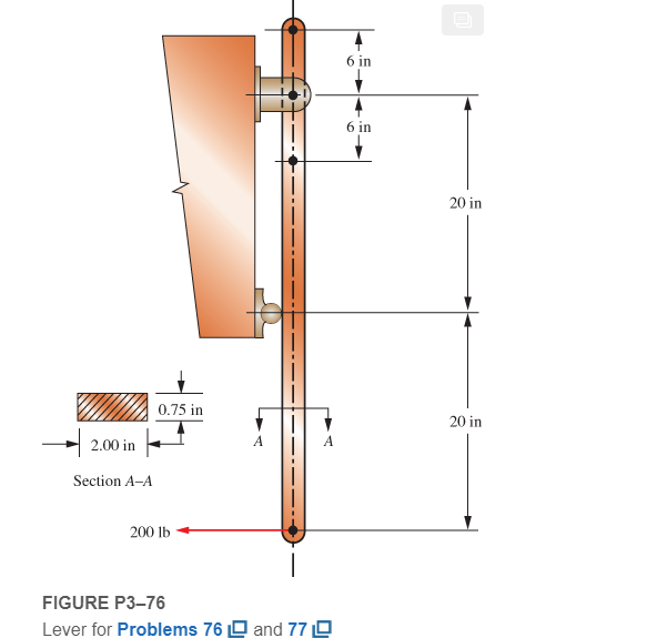
Expert Solution & Answer
Want to see the full answer?
Check out a sample textbook solution
Students have asked these similar questions
The figure below is a schematic drawing of a shaft that supports two V-belt pulleys. The loose belt tension on the pulley at A is 15% of the tension on the tight side. The shaft material has a yield strength of 300 MPa and an ultimate tensile strength of 520 MPa. Calculate the shaft diameter.
A motor transmits 180 hp to the driving pulley, in the figure assuming that A takes 40 hp and C takes 140 hp, design the shaft for an allowable shear stress of 8000 lb/in2, the speed is 630 rpm
A flange coupling having six bolts on a pitch circle radius of 300 mm connects
two hollow shafts with an outside diameter of 400 mm. The diameter of each
bolt is 65 mm and the limiting shear stresses in the bolts are to be the same as
that for the shafts, (a) Calculate the inside diameters of the shafts, (b) Take G
as 80 GPa and calculate the angle of twist in degrees over a shaft length of 5 m
for a working stress of 60 MPa.
Chapter 3 Solutions
Machine Elements in Mechanical Design (6th Edition) (What's New in Trades & Technology)
Ch. 3 - A tensile member in a machine structure is...Ch. 3 - Compute the stress in a round bar having a...Ch. 3 - Compute the stress in a rectangular bar having...Ch. 3 - A link in a packaging machine mechanism has a...Ch. 3 - Two circular rods support the 3800 lb weight of a...Ch. 3 - A tensile load of 5.00 kN is applied to a square...Ch. 3 - An aluminum rod is made in the form of a hollow...Ch. 3 - Compute the stress in the middle portion of rod AC...Ch. 3 - Compute the forces in the two angled rods in...Ch. 3 - If the rods from Problem 9 are circular, determine...
Ch. 3 - Repeat Problems 9 and 10 if the angle is 15 .Ch. 3 - Figure P312 shows a small truss spanning between...Ch. 3 - The truss shown in Figure P313 spans a total space...Ch. 3 - Figure P314 shows a short leg for a machine that...Ch. 3 - Consider the short compression member shown in...Ch. 3 - Refer Figure P38 . Each of the pins at A, B, and C...Ch. 3 - Compute the shear stress in the pins connecting...Ch. 3 - Prob. 18PCh. 3 - Prob. 19PCh. 3 - Prob. 20PCh. 3 - Prob. 21PCh. 3 - Compute the torsional shear stress in a circular...Ch. 3 - If the shaft of Problem 22 is 850 mm long and is...Ch. 3 - Compute the torsional shear stress due to a torque...Ch. 3 - Compute the torsional shear stress in a solid...Ch. 3 - Compute the torsional shear stress in a hollow...Ch. 3 - Compute the angle of twist for the hollow shaft of...Ch. 3 - A square steel bar, 25 mm on a side and 650 mm...Ch. 3 - A 3.00 in-diameter steel bar has a flat milled on...Ch. 3 - A commercial steel supplier lists rectangular...Ch. 3 - A beam is simply supported and carries the load...Ch. 3 - For each beam of Problem 31, compute its weight if...Ch. 3 - For each beam of Problem 31, compute the maximum...Ch. 3 - For the beam loading of Figure P334, draw the...Ch. 3 - For the beam loading of Figure P334, design the...Ch. 3 - Figure P336 shows a beam made from 4 in schedule...Ch. 3 - Select an aluminum I-beam shape to carry the load...Ch. 3 - Figure P338 represents a wood joist for a...Ch. 3 - For Problems 39 through 50, draw the free-body...Ch. 3 - Prob. 40PCh. 3 - For Problems 39 through 50, draw the free-body...Ch. 3 - Prob. 42PCh. 3 - Prob. 43PCh. 3 - Prob. 44PCh. 3 - For Problems 39 through 50, draw the free-body...Ch. 3 - For Problems 39 through 50, draw the free-body...Ch. 3 - For Problems 39 through 50, draw the free-body...Ch. 3 - For Problems 4850, draw the free-body diagram of...Ch. 3 - For Problems 4850, draw the free-body diagram of...Ch. 3 - Prob. 50PCh. 3 - Compute the maximum tensile stress in the bracket...Ch. 3 - Compute the maximum tensile and compressive...Ch. 3 - For the lever shown in Figure P353 (a), compute...Ch. 3 - Compute the maximum tensile stress at sections A...Ch. 3 - Prob. 55PCh. 3 - Refer to Figure P38. Compute the maximum tensile...Ch. 3 - Prob. 57PCh. 3 - Refer to P342. Compute the maximum stress in the...Ch. 3 - Refer to P343. Compute the maximum stress in the...Ch. 3 - Prob. 60PCh. 3 - Figure P361 shows a valve stem from an engine...Ch. 3 - The conveyor fixture shown in Figure P362 carries...Ch. 3 - For the flat plate in tension in Figure P363,...Ch. 3 - For Problems 64 through 68, compute the maximum...Ch. 3 - For Problems 64 through 68, compute the maximum...Ch. 3 - For Problems 64 through 68, compute the maximum...Ch. 3 - For Problems 64 through 68, compute the maximum...Ch. 3 - Prob. 68PCh. 3 - Figure P369 shows a horizontal beam supported by a...Ch. 3 - Prob. 70PCh. 3 - Prob. 71PCh. 3 - The beam shown in Figure P372 is a stepped, flat...Ch. 3 - Figure P373 shows a stepped, flat bar having a...Ch. 3 - Figure P374 shows a bracket carrying opposing...Ch. 3 - Prob. 75PCh. 3 - Figure P376 shows a lever made from a rectangular...Ch. 3 - For the lever in P376, determine the maximum...Ch. 3 - Figure P378 shows a shaft that is loaded only in...Ch. 3 - Prob. 79PCh. 3 - Prob. 80PCh. 3 - A hanger is made from ASTM A36 structural steel...Ch. 3 - A coping saw frame shown in Figure P382 is made...Ch. 3 - Prob. 83PCh. 3 - Figure P384 shows a hand garden tool used to break...Ch. 3 - Figure P385 shows a basketball backboard and goal...Ch. 3 - Prob. 86P
Knowledge Booster


Learn more about
Need a deep-dive on the concept behind this application? Look no further. Learn more about this topic, mechanical-engineering and related others by exploring similar questions and additional content below.Similar questions
- Repeat Problem 11.2-3 assuming that R= 10 kN · m/rad and L = 2 m.arrow_forwardConsider the case of shafts subjected to bending moment only. Figure Q2 shows a pair of wheels of a railway wagon that carries a load of 50kN on each axle box, acting at a distance of 100 mm outside the wheel base. The gauge of the rails is 1.4m. Figure Q2 If the stress is not to exceed 100MPa, find, the diameter of the axle between the wheels, and if a hollow circular shaft is to be used in place of the solid shaft, find the inside and outside diameter when the ratio of inside to outside diameter is 0.5.arrow_forward2. A 30-mm bolt with an initial tension of 35 kN is subjected to several types of stresses during initial tightening or due to screwing up forces. If the bolt has a core diameter of 25.7 mm and considering 5 threads are already engaged with the nut, calculate the shear stress across the thread and the crushing stress between the threads. Assume 3.5 mm as the width of the thread section at the root.arrow_forward
- A mild steel rod having a stress of 50 Mpa and having a diameter of 20 mm What is the force applied on it.arrow_forwardThe state of stress acting at a critical point on a wrench is shown in the figure. Determine the smallest yield stress for steel that might be selected for the part, based on the maximum shear stress theory.arrow_forwardA link in an automated packaging machine is a hollow tube made from 6061-T6 aluminum. Its dimensions are as follows: outside diameter = 32.0 mm, inside diameter = 28.0 mm, and length = 1.00 m. Compute the tensile force required to produce an elongation of the bar of 1.3 mm. Would the stress produced by the force just found be safe if the load is applied repeatedly?arrow_forward
- Link 2, shown in the figure, is 25 mm wide and 11 mm thick. It is made from low-carbon steel with Sy= 165 MPa. The pin joints are constructed with sufficient size and fit to provide good resistance to out-of-plane bending. Use Table 4-2 shown below for recommended values for C. Determine the following for link 2: a.)Axial Force b.)Yield factor of safety c.) In-plane buckling factor of safety and Out-plane buckling factor of safetyarrow_forwardThe compound shaft shown in Fig. P-319 is attached to rigid supports. For the bronze segment AB, the diameter is 75 mm, τ ≤ 60 MPa, and G = 35 GPa. For the steel segment BC, the diameter is 50 mm, τ ≤ 80 MPa, and G = 83 GPa. If a = 2 m and b = 1.5 m, compute the maximum torque T that can be applied.arrow_forwardThe pin in the image shown below must transfer an axial tension force of 12.7 kN. Calculate the minimum pin diameter. Use Shear stress=0.4*Yield strength. Assume material is 1020 hot-rolled steel.arrow_forward
- Given a 2meter Wide Flange steel compression member with A=4,513mm2, Ix=86,630,006mm4 and Iy=3,824,544mm4 with Fy = 345MPa. Calculate the critical buckling stress in MPa if both ends are fixed or rigid. Express your answer in 2 decimal places.arrow_forwardQ3 The figure shows a round shaft from a gear transmission. Gears are mounted at points A, C, and E. Supporting bearings are at B and D. The forces transmitted from the gears to the shaft are shown, all acting downward. Compute the maximum stress due to bending in the shaft, accounting for stress concentrations. calculate the safety factor for the material selected.if martial 4150 OQT 1300 force 1 (f1)=9.5 kn ,Force 2(f2)=13.5Kn ,Force3 (f3)=18Knarrow_forwardQ // If the value of the highest load we get from the tensile test of a wrought iron model with a circular . section is (52 kN) with an axial stress of ( 460 Mpa), calculate the diameter of the examined modelarrow_forward
arrow_back_ios
SEE MORE QUESTIONS
arrow_forward_ios
Recommended textbooks for you
 Mechanics of Materials (MindTap Course List)Mechanical EngineeringISBN:9781337093347Author:Barry J. Goodno, James M. GerePublisher:Cengage Learning
Mechanics of Materials (MindTap Course List)
Mechanical Engineering
ISBN:9781337093347
Author:Barry J. Goodno, James M. Gere
Publisher:Cengage Learning
Basic Fabrication Techniques; Author: Weld.com;https://www.youtube.com/watch?v=3OW7iRnC8Ck;License: Standard Youtube License