
Machine Elements in Mechanical Design (6th Edition) (What's New in Trades & Technology)
6th Edition
ISBN: 9780134441184
Author: Robert L. Mott, Edward M. Vavrek, Jyhwen Wang
Publisher: PEARSON
expand_more
expand_more
format_list_bulleted
Videos
Textbook Question
Chapter 3, Problem 9P
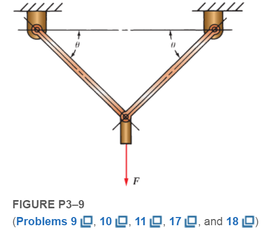
Compute the forces in the two angled rods in FigureP3−9for an applied force,
Expert Solution & Answer
Want to see the full answer?
Check out a sample textbook solution
Students have asked these similar questions
Compute the forces in the two angled rods in Figure below for an applied force, F = 1500 lb, if the angle u is 45°.
The cable carrying three 400-N loads has a sag at C of hC = 14 m. Calculate the following:
26.1 The magnitude of the tensile force in segment AB is Blank 1 N.
26.2 The magnitude of the tensile force in segment BC is Blank 2 N.
26.3 The magnitude of the tensile force in segment CD is Blank 3 N.
26.4 The magnitude of the tensile force in segment DE is Blank 4 N.
In the train bridge in the figure, select the F1 and F2 forces from 107 to 207 kN with a non-zero end. Find the force on the bar BC and whether it is the pull. ?
Chapter 3 Solutions
Machine Elements in Mechanical Design (6th Edition) (What's New in Trades & Technology)
Ch. 3 - A tensile member in a machine structure is...Ch. 3 - Compute the stress in a round bar having a...Ch. 3 - Compute the stress in a rectangular bar having...Ch. 3 - A link in a packaging machine mechanism has a...Ch. 3 - Two circular rods support the 3800 lb weight of a...Ch. 3 - A tensile load of 5.00 kN is applied to a square...Ch. 3 - An aluminum rod is made in the form of a hollow...Ch. 3 - Compute the stress in the middle portion of rod AC...Ch. 3 - Compute the forces in the two angled rods in...Ch. 3 - If the rods from Problem 9 are circular, determine...
Ch. 3 - Repeat Problems 9 and 10 if the angle is 15 .Ch. 3 - Figure P312 shows a small truss spanning between...Ch. 3 - The truss shown in Figure P313 spans a total space...Ch. 3 - Figure P314 shows a short leg for a machine that...Ch. 3 - Consider the short compression member shown in...Ch. 3 - Refer Figure P38 . Each of the pins at A, B, and C...Ch. 3 - Compute the shear stress in the pins connecting...Ch. 3 - Prob. 18PCh. 3 - Prob. 19PCh. 3 - Prob. 20PCh. 3 - Prob. 21PCh. 3 - Compute the torsional shear stress in a circular...Ch. 3 - If the shaft of Problem 22 is 850 mm long and is...Ch. 3 - Compute the torsional shear stress due to a torque...Ch. 3 - Compute the torsional shear stress in a solid...Ch. 3 - Compute the torsional shear stress in a hollow...Ch. 3 - Compute the angle of twist for the hollow shaft of...Ch. 3 - A square steel bar, 25 mm on a side and 650 mm...Ch. 3 - A 3.00 in-diameter steel bar has a flat milled on...Ch. 3 - A commercial steel supplier lists rectangular...Ch. 3 - A beam is simply supported and carries the load...Ch. 3 - For each beam of Problem 31, compute its weight if...Ch. 3 - For each beam of Problem 31, compute the maximum...Ch. 3 - For the beam loading of Figure P334, draw the...Ch. 3 - For the beam loading of Figure P334, design the...Ch. 3 - Figure P336 shows a beam made from 4 in schedule...Ch. 3 - Select an aluminum I-beam shape to carry the load...Ch. 3 - Figure P338 represents a wood joist for a...Ch. 3 - For Problems 39 through 50, draw the free-body...Ch. 3 - Prob. 40PCh. 3 - For Problems 39 through 50, draw the free-body...Ch. 3 - Prob. 42PCh. 3 - Prob. 43PCh. 3 - Prob. 44PCh. 3 - For Problems 39 through 50, draw the free-body...Ch. 3 - For Problems 39 through 50, draw the free-body...Ch. 3 - For Problems 39 through 50, draw the free-body...Ch. 3 - For Problems 4850, draw the free-body diagram of...Ch. 3 - For Problems 4850, draw the free-body diagram of...Ch. 3 - Prob. 50PCh. 3 - Compute the maximum tensile stress in the bracket...Ch. 3 - Compute the maximum tensile and compressive...Ch. 3 - For the lever shown in Figure P353 (a), compute...Ch. 3 - Compute the maximum tensile stress at sections A...Ch. 3 - Prob. 55PCh. 3 - Refer to Figure P38. Compute the maximum tensile...Ch. 3 - Prob. 57PCh. 3 - Refer to P342. Compute the maximum stress in the...Ch. 3 - Refer to P343. Compute the maximum stress in the...Ch. 3 - Prob. 60PCh. 3 - Figure P361 shows a valve stem from an engine...Ch. 3 - The conveyor fixture shown in Figure P362 carries...Ch. 3 - For the flat plate in tension in Figure P363,...Ch. 3 - For Problems 64 through 68, compute the maximum...Ch. 3 - For Problems 64 through 68, compute the maximum...Ch. 3 - For Problems 64 through 68, compute the maximum...Ch. 3 - For Problems 64 through 68, compute the maximum...Ch. 3 - Prob. 68PCh. 3 - Figure P369 shows a horizontal beam supported by a...Ch. 3 - Prob. 70PCh. 3 - Prob. 71PCh. 3 - The beam shown in Figure P372 is a stepped, flat...Ch. 3 - Figure P373 shows a stepped, flat bar having a...Ch. 3 - Figure P374 shows a bracket carrying opposing...Ch. 3 - Prob. 75PCh. 3 - Figure P376 shows a lever made from a rectangular...Ch. 3 - For the lever in P376, determine the maximum...Ch. 3 - Figure P378 shows a shaft that is loaded only in...Ch. 3 - Prob. 79PCh. 3 - Prob. 80PCh. 3 - A hanger is made from ASTM A36 structural steel...Ch. 3 - A coping saw frame shown in Figure P382 is made...Ch. 3 - Prob. 83PCh. 3 - Figure P384 shows a hand garden tool used to break...Ch. 3 - Figure P385 shows a basketball backboard and goal...Ch. 3 - Prob. 86P
Knowledge Booster


Learn more about
Need a deep-dive on the concept behind this application? Look no further. Learn more about this topic, mechanical-engineering and related others by exploring similar questions and additional content below.Similar questions
- Repeat Problem 11.2-3 assuming that R= 10 kN · m/rad and L = 2 m.arrow_forwardA safety valve on the top of a tank containing steam under pressure p has a discharge hole of diameter d(see figure). The valve is designed to release the steam when the pressure reaches the value Pmax If the natural length of the spring, is L and its stiffness is k, what should be the dimension ft of the valve? (Express your result as a formula for h.)arrow_forwardThe spinning wheel, as shown in the figure, is subjected to a load of 200 lb. F calculate the horizontal force vectorarrow_forward
- The force P3 to make it to equilibrium in kN is The Stress in section 1 in N/mm2 is The Compressive Stress in section 2 in N/mm2 is The stress in section 3 in N/mm2 is The total change in length in x10-3 mm isarrow_forwardFigure Q3 shows a steel bar of diameter 16 mm and length 600 mm subjected to axial forces.If E = 210×103 N/mm2for steel, determine the change in its length.arrow_forwardKindly compute all the internal forces in every cable in the figure below. and show the complete solutions.arrow_forward
- Sketch a free body diagram of each element in the figure. Compute the magnitude and direction of each force using an algebraic or vector method, as specified.arrow_forwardThe bolt AB in (Figure 1) has a diameter of 18 mm and passes through a sleeve that has an inner diameter of 42 mm and an outer diameter of 52 mm. The bolt and sleeve are made of A-36 steel and are secured to the rigid brackets as shown. If the bolt length is 220 mm and the sleeve length is 200 mm, determine the tension in the bolt when a force of 50 kN is applied to the brackets.arrow_forwardDetermine the force Vectors F = 90 N and F43 in the four bar mechanism shown in figure below. Draw the force diagram for the link QB. OQ is 80 Cm. OA is 50 Cm. AB is 70 Cm. QB is 60 Cm. QE is 34 Cm. Link QB at 77 degrees with horizontal. Link AB is 13 degrees with horizontal. Force F is at 32 degrees with horizontal. Link OA is at 60 degrees with horizontal.arrow_forward
- Find the Axial Forces in members 1 - 5. Find the Displacement Displacement of joint A (mm, positive right and up) for both Horizontal and Verticalarrow_forwardThe system shown in the figure is subjected to a force of F = 509 N 1) Calculate the magnitude of the force on support B. Show all the complete free-body diagrams required to obtain this and all answers. This is the numerical answer you provide in this question. 2) Calculate the horizontal and vertical reactions at support A. Write your answer to the nearest integer. Don't forget the units. In an additional question you must upload a document with the procedure carried out to obtain your answer.arrow_forwardFigure Q2 shows an arrangement used to transfer materials F to a construction site. The rod OB is fixed at datum O. One of the systems used have dimension and loads as given in Table Q2. During operation, Pulley A is rotated as shown to move the load upwards. The inclination angle of rod OB is θ = 45O. Determine: Stress in Rope 1 (in MPa) Stress in Rope 2 (in MPa) Extension in Rope 2 (in mm) The minimum diameter of Rope 2 (in mm) if the stress is at yieldarrow_forward
arrow_back_ios
SEE MORE QUESTIONS
arrow_forward_ios
Recommended textbooks for you
 Mechanics of Materials (MindTap Course List)Mechanical EngineeringISBN:9781337093347Author:Barry J. Goodno, James M. GerePublisher:Cengage Learning
Mechanics of Materials (MindTap Course List)
Mechanical Engineering
ISBN:9781337093347
Author:Barry J. Goodno, James M. Gere
Publisher:Cengage Learning
Mechanical SPRING DESIGN Strategy and Restrictions in Under 15 Minutes!; Author: Less Boring Lectures;https://www.youtube.com/watch?v=dsWQrzfQt3s;License: Standard Youtube License