
Machine Elements in Mechanical Design (6th Edition) (What's New in Trades & Technology)
6th Edition
ISBN: 9780134441184
Author: Robert L. Mott, Edward M. Vavrek, Jyhwen Wang
Publisher: PEARSON
expand_more
expand_more
format_list_bulleted
Videos
Textbook Question
Chapter 3, Problem 63P
For the flat plate in tension in Figure P3−63, compute the stress at each hole, assuming that the holes are sufficiently far apart that their effects do not interact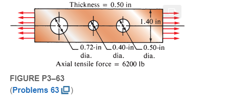
Expert Solution & Answer
Want to see the full answer?
Check out a sample textbook solution
Students have asked these similar questions
What would be the compressive stress in MPa developed in the silica glass furnace tube constrained in the way illustrated in the figure if it were heated to 1000C?
Figure Q5 shows a thick cylinder of 50 mm internal radius and 130 mm outer radius is subjected to an internal pressure of 60 MN/m2 and an external pressure of 30 MN/m2.
Determine the hoop and radial stresses at the inside and outside of the cylinder together with the longitudinal stress if the cylinder is assumed to have closed ends using analytical and graphical approaches
As shown in the figure, a bolt with a diameter of 10 mm is affected by three separate forces in different directions. (a) the net effect of the three forces is desired to be in the y direction. In this context, calculate the Force F as [kN]. (b) find the tensile stress generated in the Bolt as [MPa], taking into account the F value found.
Chapter 3 Solutions
Machine Elements in Mechanical Design (6th Edition) (What's New in Trades & Technology)
Ch. 3 - A tensile member in a machine structure is...Ch. 3 - Compute the stress in a round bar having a...Ch. 3 - Compute the stress in a rectangular bar having...Ch. 3 - A link in a packaging machine mechanism has a...Ch. 3 - Two circular rods support the 3800 lb weight of a...Ch. 3 - A tensile load of 5.00 kN is applied to a square...Ch. 3 - An aluminum rod is made in the form of a hollow...Ch. 3 - Compute the stress in the middle portion of rod AC...Ch. 3 - Compute the forces in the two angled rods in...Ch. 3 - If the rods from Problem 9 are circular, determine...
Ch. 3 - Repeat Problems 9 and 10 if the angle is 15 .Ch. 3 - Figure P312 shows a small truss spanning between...Ch. 3 - The truss shown in Figure P313 spans a total space...Ch. 3 - Figure P314 shows a short leg for a machine that...Ch. 3 - Consider the short compression member shown in...Ch. 3 - Refer Figure P38 . Each of the pins at A, B, and C...Ch. 3 - Compute the shear stress in the pins connecting...Ch. 3 - Prob. 18PCh. 3 - Prob. 19PCh. 3 - Prob. 20PCh. 3 - Prob. 21PCh. 3 - Compute the torsional shear stress in a circular...Ch. 3 - If the shaft of Problem 22 is 850 mm long and is...Ch. 3 - Compute the torsional shear stress due to a torque...Ch. 3 - Compute the torsional shear stress in a solid...Ch. 3 - Compute the torsional shear stress in a hollow...Ch. 3 - Compute the angle of twist for the hollow shaft of...Ch. 3 - A square steel bar, 25 mm on a side and 650 mm...Ch. 3 - A 3.00 in-diameter steel bar has a flat milled on...Ch. 3 - A commercial steel supplier lists rectangular...Ch. 3 - A beam is simply supported and carries the load...Ch. 3 - For each beam of Problem 31, compute its weight if...Ch. 3 - For each beam of Problem 31, compute the maximum...Ch. 3 - For the beam loading of Figure P334, draw the...Ch. 3 - For the beam loading of Figure P334, design the...Ch. 3 - Figure P336 shows a beam made from 4 in schedule...Ch. 3 - Select an aluminum I-beam shape to carry the load...Ch. 3 - Figure P338 represents a wood joist for a...Ch. 3 - For Problems 39 through 50, draw the free-body...Ch. 3 - Prob. 40PCh. 3 - For Problems 39 through 50, draw the free-body...Ch. 3 - Prob. 42PCh. 3 - Prob. 43PCh. 3 - Prob. 44PCh. 3 - For Problems 39 through 50, draw the free-body...Ch. 3 - For Problems 39 through 50, draw the free-body...Ch. 3 - For Problems 39 through 50, draw the free-body...Ch. 3 - For Problems 4850, draw the free-body diagram of...Ch. 3 - For Problems 4850, draw the free-body diagram of...Ch. 3 - Prob. 50PCh. 3 - Compute the maximum tensile stress in the bracket...Ch. 3 - Compute the maximum tensile and compressive...Ch. 3 - For the lever shown in Figure P353 (a), compute...Ch. 3 - Compute the maximum tensile stress at sections A...Ch. 3 - Prob. 55PCh. 3 - Refer to Figure P38. Compute the maximum tensile...Ch. 3 - Prob. 57PCh. 3 - Refer to P342. Compute the maximum stress in the...Ch. 3 - Refer to P343. Compute the maximum stress in the...Ch. 3 - Prob. 60PCh. 3 - Figure P361 shows a valve stem from an engine...Ch. 3 - The conveyor fixture shown in Figure P362 carries...Ch. 3 - For the flat plate in tension in Figure P363,...Ch. 3 - For Problems 64 through 68, compute the maximum...Ch. 3 - For Problems 64 through 68, compute the maximum...Ch. 3 - For Problems 64 through 68, compute the maximum...Ch. 3 - For Problems 64 through 68, compute the maximum...Ch. 3 - Prob. 68PCh. 3 - Figure P369 shows a horizontal beam supported by a...Ch. 3 - Prob. 70PCh. 3 - Prob. 71PCh. 3 - The beam shown in Figure P372 is a stepped, flat...Ch. 3 - Figure P373 shows a stepped, flat bar having a...Ch. 3 - Figure P374 shows a bracket carrying opposing...Ch. 3 - Prob. 75PCh. 3 - Figure P376 shows a lever made from a rectangular...Ch. 3 - For the lever in P376, determine the maximum...Ch. 3 - Figure P378 shows a shaft that is loaded only in...Ch. 3 - Prob. 79PCh. 3 - Prob. 80PCh. 3 - A hanger is made from ASTM A36 structural steel...Ch. 3 - A coping saw frame shown in Figure P382 is made...Ch. 3 - Prob. 83PCh. 3 - Figure P384 shows a hand garden tool used to break...Ch. 3 - Figure P385 shows a basketball backboard and goal...Ch. 3 - Prob. 86P
Knowledge Booster


Learn more about
Need a deep-dive on the concept behind this application? Look no further. Learn more about this topic, mechanical-engineering and related others by exploring similar questions and additional content below.Similar questions
- Solve the preceding problem for sx= 11 MPa and ??y= -20 MPa (see figure).arrow_forwardA flat bar of width b and thickness t has a hole of diameter d drilled through it (see figure). The hole may have any diameter that will fit within the bar. What is the maximum permissible tensile load Pmaxif the allowable tensile stress in the material is st?arrow_forwardA cylinder filled with oil is under pressure from a piston, as shown in the figure. The diameter d of the piston is 1,80 in. and the compressive force F is 3500 lb. The maximum allowable shear stress t^^, in the wall of the cylinder is 5500 psi. What is the minimum permissible thickness t„± of the cylinder wall? (Sec figurearrow_forward
- A spherical balloon is filled with a gas. The outer diameter of the balloon is 20 in. and the thickness is 0,012 in. Calculate the maximum permissible pressure in the balloon if the allowable tensile stress and the allowable shear stress in the balloon are 1 ksi and 0.3 ksi, respectively.arrow_forwardAn element in plane stress is subjected to stresses ??x= 5750 psi, sy = 1100 psi, and txy= 750 psi (see the figure for Problem 7.3-1). Determine the principal stresses and show them on a sketch of a properly oriented element.arrow_forward(a) Solve part (a) of the preceding problem if the pressure is 8.5 psi, the diameter is 10 in., the wall thickness is 0,05 in., the modulus of elasticity is 200 psi, and Poisson's ratio is 0.48. (b) If the strain must be limited to 1.01, find the maximum acceptable inflation pressurearrow_forward
- A spherical steel pressure vessel (diameter 500 mm, thickness 10 mm) is coated with brittle lacquer that cracks when the strain reaches 150 X 10~ (see figure). (a) What internal pressure p will cause the lacquer to develop cracks? (Assume E = 205 GPa and v = 0.30.) (b) If the strain is measured at 125 x 10-6, what is the internal pressure at that point?arrow_forwardFigure P3–73 shows an aluminum cylinder being capped by two end plates that are held in position with four steel tie-rods. A clamping force is created by tightening the nuts on the ends of the tie-rods. Compute the stress in the cylinder and the tie-rods if the nuts are turned one full turn from the handtight condition.arrow_forwardA rubber block with dimensions 120x120x120 mm is a rigid mold It is compressed with a vertical force of F = 120 kN inside the cavity. In the rubber block, 1-) Can you find the vertical stress (in the y direction). 2-) The shape formed in the vertical (y direction) Can you find the value of the change (mm). (Note: The mold cavity is in the shape of a prismatic box. Vertical Force F is applied in the y direction. x and z directions are closed) Rubber block, (Elasticity modulus E = 820 MPa , Poisson ratio v=0,4)arrow_forward
- Two disks are connected by four rods, as shown in Figure P3–70. All rods are 6.0 mm in diameter and have the same length. Two rods are steel (E = 207 GPa), and two are aluminum (E = 69 GPa). Compute the stress in each rod when an axial tensile force of 11.3 kN is applied to the disks.arrow_forward3. A 5/8 in diameter circular rod supports part of a storage shelf in a warehouse. As products areloaded and unloaded, the rod is subjected to a tensile load that varies from 1800 to 150 lb.Draw a sketch of the variation of stress versus time, and compute the maximum stress,minimum stress, mean stress, alternating stress, and stress ratio, R. please also give the FBD every calculation, thanky ouarrow_forwardThe carrier plate in the figure is attached to the column with the help of 3 bolts. A vertical force of 17 kN is applied to the carrier plate from the same plane as the plate. Calculate the maximum resultant force and stress that will occur in the bolts.arrow_forward
arrow_back_ios
SEE MORE QUESTIONS
arrow_forward_ios
Recommended textbooks for you
 Mechanics of Materials (MindTap Course List)Mechanical EngineeringISBN:9781337093347Author:Barry J. Goodno, James M. GerePublisher:Cengage Learning
Mechanics of Materials (MindTap Course List)
Mechanical Engineering
ISBN:9781337093347
Author:Barry J. Goodno, James M. Gere
Publisher:Cengage Learning
Mechanical SPRING DESIGN Strategy and Restrictions in Under 15 Minutes!; Author: Less Boring Lectures;https://www.youtube.com/watch?v=dsWQrzfQt3s;License: Standard Youtube License