
Machine Elements in Mechanical Design (6th Edition) (What's New in Trades & Technology)
6th Edition
ISBN: 9780134441184
Author: Robert L. Mott, Edward M. Vavrek, Jyhwen Wang
Publisher: PEARSON
expand_more
expand_more
format_list_bulleted
Concept explainers
Videos
Textbook Question
Chapter 3, Problem 61P
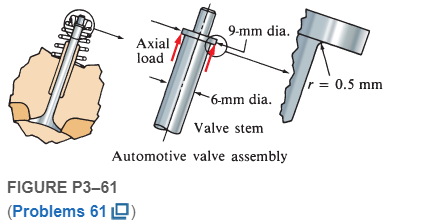
Figure P3−61 shows a valve stem from an engine subjected to an axial tensile load applied by the valve spring. For a force of 1.25 kN, compute the maximum stress at the fillet under the shoulder.
Expert Solution & Answer
Want to see the full answer?
Check out a sample textbook solution
Students have asked these similar questions
simple turnbuckle arrangement is constructed from a 40 mm outside diameter tube threaded internally
at each end to take two rods of 25 mm outside diameter with threaded ends. What will be the nominal stresses set up
in the tube and the rods, ignoring thread depth, when the turnbuckle carries an axial load of 30 kN? Assuming a
sufficient strength of thread, what maximum load can be transmitted by the turnbuckle if the maximum stress 1s
limited to 180 MN/m*?
A cylindrical pressure vessel with a diameter of 600 mm is to be fabricated from steel plates of thickness 16 mm. Compute the maximum value of the internal pressure it can hold inside if the tangential stress is limited to 140 MPa with a safety factor of 2.4.
a. 4.28 MPa
b. 5.28 MPa
c. 3.11 MPa
d. 6.09 MPa
Q3 The figure shows a round shaft from a gear transmission. Gears are mounted at points A, C, and E. Supporting bearings are at B and D. The forces transmitted from the gears to the shaft are shown, all acting downward. Compute the maximum stress due to bending in the shaft, accounting for stress concentrations. calculate the safety factor for the material selected.if martial 4150 OQT 1300
force 1 (f1)=9.5 kn ,Force 2(f2)=13.5Kn ,Force3 (f3)=18Kn
Chapter 3 Solutions
Machine Elements in Mechanical Design (6th Edition) (What's New in Trades & Technology)
Ch. 3 - A tensile member in a machine structure is...Ch. 3 - Compute the stress in a round bar having a...Ch. 3 - Compute the stress in a rectangular bar having...Ch. 3 - A link in a packaging machine mechanism has a...Ch. 3 - Two circular rods support the 3800 lb weight of a...Ch. 3 - A tensile load of 5.00 kN is applied to a square...Ch. 3 - An aluminum rod is made in the form of a hollow...Ch. 3 - Compute the stress in the middle portion of rod AC...Ch. 3 - Compute the forces in the two angled rods in...Ch. 3 - If the rods from Problem 9 are circular, determine...
Ch. 3 - Repeat Problems 9 and 10 if the angle is 15 .Ch. 3 - Figure P312 shows a small truss spanning between...Ch. 3 - The truss shown in Figure P313 spans a total space...Ch. 3 - Figure P314 shows a short leg for a machine that...Ch. 3 - Consider the short compression member shown in...Ch. 3 - Refer Figure P38 . Each of the pins at A, B, and C...Ch. 3 - Compute the shear stress in the pins connecting...Ch. 3 - Prob. 18PCh. 3 - Prob. 19PCh. 3 - Prob. 20PCh. 3 - Prob. 21PCh. 3 - Compute the torsional shear stress in a circular...Ch. 3 - If the shaft of Problem 22 is 850 mm long and is...Ch. 3 - Compute the torsional shear stress due to a torque...Ch. 3 - Compute the torsional shear stress in a solid...Ch. 3 - Compute the torsional shear stress in a hollow...Ch. 3 - Compute the angle of twist for the hollow shaft of...Ch. 3 - A square steel bar, 25 mm on a side and 650 mm...Ch. 3 - A 3.00 in-diameter steel bar has a flat milled on...Ch. 3 - A commercial steel supplier lists rectangular...Ch. 3 - A beam is simply supported and carries the load...Ch. 3 - For each beam of Problem 31, compute its weight if...Ch. 3 - For each beam of Problem 31, compute the maximum...Ch. 3 - For the beam loading of Figure P334, draw the...Ch. 3 - For the beam loading of Figure P334, design the...Ch. 3 - Figure P336 shows a beam made from 4 in schedule...Ch. 3 - Select an aluminum I-beam shape to carry the load...Ch. 3 - Figure P338 represents a wood joist for a...Ch. 3 - For Problems 39 through 50, draw the free-body...Ch. 3 - Prob. 40PCh. 3 - For Problems 39 through 50, draw the free-body...Ch. 3 - Prob. 42PCh. 3 - Prob. 43PCh. 3 - Prob. 44PCh. 3 - For Problems 39 through 50, draw the free-body...Ch. 3 - For Problems 39 through 50, draw the free-body...Ch. 3 - For Problems 39 through 50, draw the free-body...Ch. 3 - For Problems 4850, draw the free-body diagram of...Ch. 3 - For Problems 4850, draw the free-body diagram of...Ch. 3 - Prob. 50PCh. 3 - Compute the maximum tensile stress in the bracket...Ch. 3 - Compute the maximum tensile and compressive...Ch. 3 - For the lever shown in Figure P353 (a), compute...Ch. 3 - Compute the maximum tensile stress at sections A...Ch. 3 - Prob. 55PCh. 3 - Refer to Figure P38. Compute the maximum tensile...Ch. 3 - Prob. 57PCh. 3 - Refer to P342. Compute the maximum stress in the...Ch. 3 - Refer to P343. Compute the maximum stress in the...Ch. 3 - Prob. 60PCh. 3 - Figure P361 shows a valve stem from an engine...Ch. 3 - The conveyor fixture shown in Figure P362 carries...Ch. 3 - For the flat plate in tension in Figure P363,...Ch. 3 - For Problems 64 through 68, compute the maximum...Ch. 3 - For Problems 64 through 68, compute the maximum...Ch. 3 - For Problems 64 through 68, compute the maximum...Ch. 3 - For Problems 64 through 68, compute the maximum...Ch. 3 - Prob. 68PCh. 3 - Figure P369 shows a horizontal beam supported by a...Ch. 3 - Prob. 70PCh. 3 - Prob. 71PCh. 3 - The beam shown in Figure P372 is a stepped, flat...Ch. 3 - Figure P373 shows a stepped, flat bar having a...Ch. 3 - Figure P374 shows a bracket carrying opposing...Ch. 3 - Prob. 75PCh. 3 - Figure P376 shows a lever made from a rectangular...Ch. 3 - For the lever in P376, determine the maximum...Ch. 3 - Figure P378 shows a shaft that is loaded only in...Ch. 3 - Prob. 79PCh. 3 - Prob. 80PCh. 3 - A hanger is made from ASTM A36 structural steel...Ch. 3 - A coping saw frame shown in Figure P382 is made...Ch. 3 - Prob. 83PCh. 3 - Figure P384 shows a hand garden tool used to break...Ch. 3 - Figure P385 shows a basketball backboard and goal...Ch. 3 - Prob. 86P
Knowledge Booster


Learn more about
Need a deep-dive on the concept behind this application? Look no further. Learn more about this topic, mechanical-engineering and related others by exploring similar questions and additional content below.Similar questions
- A safety valve on the top of a tank containing steam under pressure p has a discharge hole of diameter d(see figure). The valve is designed to release the steam when the pressure reaches the value Pmax If the natural length of the spring, is L and its stiffness is k, what should be the dimension ft of the valve? (Express your result as a formula for h.)arrow_forwardFigure P3–73 shows an aluminum cylinder being capped by two end plates that are held in position with four steel tie-rods. A clamping force is created by tightening the nuts on the ends of the tie-rods. Compute the stress in the cylinder and the tie-rods if the nuts are turned one full turn from the handtight condition.arrow_forwardProblem 4 only, solve carefully, include the units in every step and draw the diagram. Thanks! A steel tie rod on bridge must be made to withstand a pull of 5000 lbs. Find the diameter of the rod assuming a factor ofsafety of 4 and allowable stress of 14,000 psarrow_forward
- A motor transmits 180 hp to the driving pulley, in the figure assuming that A takes 40 hp and C takes 140 hp, design the shaft for an allowable shear stress of 8000 lb/in2, the speed is 630 rpmarrow_forwardCalculate the maximum and minimum normal stresses experienced by the lever indicated in the image.arrow_forwardA single-piece bicycle crank is shown below under the following load: the rider pedals forward with a vertical force Fp = 500 N on the left pedal and no force on the right pedal. The chain exerts a force Fc on the chainring. The spindle is a solid cylinder with a diameter d = 16 mm. 1. Find the maximum normal stress and shear stress at cross-section y-y in image. Indicate the locations on the given cross section view where they act.arrow_forward
- . A steel boiler 2.5 m in diameter has a wall thickness of 25 mm. The internal pressure is 1.6 MPa. Calculate the factor of safety if the maximum permissible stress for it is 250 MPa?arrow_forwardProblem 1 only, solve carefully, include the units and dra the diagram. Thanks! . A taper pin is used to fix a lever to a shaft, if it is to transmit a maximum torque of 850 in-lb. The shaft diameter is 1.75inches and has an ultimate stress of 60,000 psi, if the factor of safety is 3, findA. Force that will shear the pin, kNB. Shear pin diameter, mmarrow_forwardThe figure below is a schematic drawing of a shaft that supports two V-belt pulleys. The loose belt tension on the pulley at A is 15% of the tension on the tight side. The shaft material has a yield strength of 300 MPa and an ultimate tensile strength of 520 MPa. Calculate the shaft diameter.arrow_forward
- PROBLEM 2A tri metallic bar is uniformly compressed by an axial force P=12kN applied through a rigid end plate. The bar consists of a circular steel core surrounded by brass and copper tubes. The steel core has a diameter 10mm, the brass tube has an oute diameter of 15mm and the copper tube has an outer diameter of 20mm. E for steel =210Gpa, E for brass =100GPa and E for copper is 120GPa. Calculate the compressive stress of each metal due to force P.arrow_forwardThe pin in the image shown below must transfer an axial tension force of 12.7 kN. Calculate the minimum pin diameter. Use Shear stress=0.4*Yield strength. Assume material is 1020 hot-rolled steel.arrow_forwardThe pin in the image shown must transfer an axial tension force of 12.7 kN. Calculate the minimum pin diameter. Use Shear Stress = 0.4*Yield strength. Assume material is 1020 hot-rolled steel.arrow_forward
arrow_back_ios
SEE MORE QUESTIONS
arrow_forward_ios
Recommended textbooks for you
 Mechanics of Materials (MindTap Course List)Mechanical EngineeringISBN:9781337093347Author:Barry J. Goodno, James M. GerePublisher:Cengage Learning
Mechanics of Materials (MindTap Course List)
Mechanical Engineering
ISBN:9781337093347
Author:Barry J. Goodno, James M. Gere
Publisher:Cengage Learning
Solids: Lesson 53 - Slope and Deflection of Beams Intro; Author: Jeff Hanson;https://www.youtube.com/watch?v=I7lTq68JRmY;License: Standard YouTube License, CC-BY