
Mechanics of Materials (MindTap Course List)
9th Edition
ISBN: 9781337093347
Author: Barry J. Goodno, James M. Gere
Publisher: Cengage Learning
expand_more
expand_more
format_list_bulleted
Concept explainers
Videos
Textbook Question
Chapter 4, Problem 4.3.27P
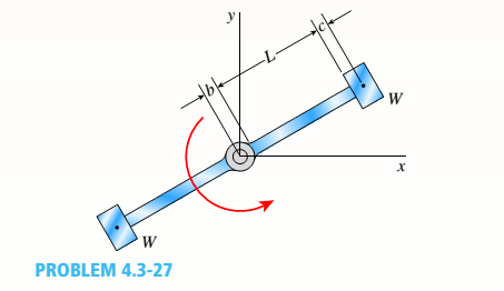
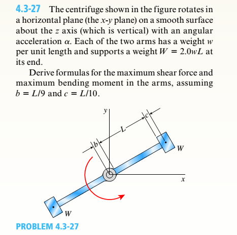
The centrifuge shown in the figure rotates in a horizontal plane (the x-y plane) on a smooth surface about the z axis (which is vertical) with an angular acceleration a. Each of the two arms has a weight w per unit length and supports a weight W = 2B/L at its end.
Derive formulas for the maximum shear force and maximum bending moment in the arms, assuming b = L/9 and c = L/10.
Expert Solution & Answer

Trending nowThis is a popular solution!

Chapter 4 Solutions
Mechanics of Materials (MindTap Course List)
Ch. 4 - Calculate the shear force V and bending moment...Ch. 4 - Determine the shear force V and bending moment M...Ch. 4 - Determine the shear force V and bending moment M...Ch. 4 - Calculate the shear force V and bending moment M...Ch. 4 - Consider the beam with an overhang shown in the...Ch. 4 - The beam ABC shown in the figure is simply...Ch. 4 - The beam ABCD shown in the figure has overhangs at...Ch. 4 - At a full d raw, an archer applies a pull of 130 N...Ch. 4 - A curved bar ABC is subjected to loads in the form...Ch. 4 - Under cruising conditions, the distributed load...
Ch. 4 - A beam ABCD with a vertical arm CE is supported as...Ch. 4 - A simply supported beam AB supports a trapezoid...Ch. 4 - Beam ABCD represents a reinforced-concrete...Ch. 4 - Find shear (V) and moment (M) at x = 3L/4 for the...Ch. 4 - Find expressions for shear force V and moment M at...Ch. 4 - Find expressions for shear force V and moment Mat...Ch. 4 - Find expressions for shear force V and moment Mat...Ch. 4 - Find expressions for shear force V and moment M at...Ch. 4 - Find expressions for shear force V and moment M at...Ch. 4 - Find expressions for shear force V and moment M at...Ch. 4 - A cable with force P is attached to a frame at A...Ch. 4 - Find expressions for shear force V and moment M at...Ch. 4 - A cable with force P is attached to a frame at D...Ch. 4 - Frame ABCD carries two concentrated loads (2P at T...Ch. 4 - Frame ABC has a moment release just left of joint...Ch. 4 - The simply supported beam ABCD is loaded by a...Ch. 4 - The centrifuge shown in the figure rotates in a...Ch. 4 - Draw the shear-Force and bending-moment diagrams...Ch. 4 - A simple beam AB is subjected to a counter...Ch. 4 - Draw the shear-force and bending-moment diagrams...Ch. 4 - The cantilever beam AB shown in the figure is...Ch. 4 - Cantilever beam AB carries an upward uniform load...Ch. 4 - The simple beam AB shown in the figure is...Ch. 4 - A simple beam AB subjected to couples M1and 3M2...Ch. 4 - A simply supported beam ABC is loaded by a...Ch. 4 - A simply supported beam ABC is loaded at the end...Ch. 4 - A beam ABC is simply supported at A and B and has...Ch. 4 - Beam ABCD is simply supported at B and C and has...Ch. 4 - Draw the shear-force and bending-moment diagrams...Ch. 4 - The simple beam AB supports a triangular load of...Ch. 4 - The beam AB shown in the figure supports a uniform...Ch. 4 - A cantilever beam AB supports a couple and a...Ch. 4 - The cantilever beam A B shown in the figure is...Ch. 4 - Beam ABC has simple supports at .A and B. an...Ch. 4 - Beam ABC with an overhang at one end supports a...Ch. 4 - Consider the two beams shown in the figures. Which...Ch. 4 - The three beams in the figure have the same...Ch. 4 - The beam ABC shown in the figure is simply...Ch. 4 - A simple beam AB is loaded by two segments of...Ch. 4 - Two beams (see figure) are loaded the same and...Ch. 4 - The beam A BCD shown in the figure has overhangs...Ch. 4 - A beam ABCD with a vertical arm CE is supported as...Ch. 4 - Beams ABC and CD are supported at A,C, and D and...Ch. 4 - The simple beam ACE shown in the figure is...Ch. 4 - A beam with simple supports is subjected to a...Ch. 4 - A beam of length L is designed to support a...Ch. 4 - The compound beam ABCDE shown in the figure...Ch. 4 - Draw the shear-force and bending-moment diagrams...Ch. 4 - The shear-force diagram for a simple beam is shown...Ch. 4 - The shear-force diagram for a beam is shown in the...Ch. 4 - A compound beam (see figure) has an internal...Ch. 4 - A compound beam (see figure) has an shear release...Ch. 4 - A simple beam AB supports two connected wheel...Ch. 4 - The inclined beam represents a ladder with the...Ch. 4 - Beam ABC is supported by a tie rod CD as shown....Ch. 4 - A plane frame (see figure) consists of column AB...Ch. 4 - The plane frame shown in the figure is part of an...
Knowledge Booster


Learn more about
Need a deep-dive on the concept behind this application? Look no further. Learn more about this topic, mechanical-engineering and related others by exploring similar questions and additional content below.Similar questions
- At a full d raw, an archer applies a pull of 130 N to the bowstring of the bow shown in the figure. Determine the bending moment at the midpoint of the bow.arrow_forwardA freight-car axle AS is loaded approximately as shown in the figure, with the forces P representing the car loads (transmitted to the axle through the axle boxes) and the forces R representing the rail loads (transmitted to the axle through the wheels). The diameter of the axle is d = 82 mm, the distance between centers of the rails is Z., and the distance between the forces P and R is A = 220 mm. Calculate the maximum bending stress vmaxin the axle if P = 50 kN.arrow_forwardFind expressions for shear force V and moment Mat x = 2L/3 of beam (a) in terms of peak load intensity q0and beam length variable L. Repeat for beam (b) but at x = L/2.arrow_forward
- The simple beam ACE shown in the figure is subjected to a triangular load of maximum intensity q0= 200 lb/ft at a = 8 ft and a concentrated moment M = 400 Ib-ft at A. Draw the shear-force and bending-moment diagrams for this beam, Find the value of distanced that results in the maximum moment occurring at L/2. Draw the shear-force and bending-moment diagrams for this case. Find the value of distance a for which Mmaxis the largest possible value.arrow_forwardA beam ABCD with a vertical arm CE is supported as a simple beam al A and D (see figure part a). A cable passes over a small pulley that is attached to the arm at E. One end of the cable is attached to the beam at point B. (a) What is the force P in the cable if the bending moment in the beam just lo the left of point C is equal numerically to 640 lb-ft? Note: Disregard the widths of the beam and vertical arm and use centerline dimensions when making calculations. (b) Repeat part (a) if a roller support is added at C and a shear release is inserted just left of C (see figure part b).arrow_forwardFind expressions for shear force V and moment M at x = x0of beam AB in terms of peak load intensity q0and beam length variable L. Let x0= 2L/3.arrow_forward
- A beam ABCD with a vertical arm CE is supported as a simple beam at .1 and D (see figure). A cable passes over a small pulley that is attached to the arm at E. One end of the cable is attached to the beam at point B. The tensile force in the cable is 1800 lb. Draw the shear-Force and bending-moment diagrams for beam A BCD. Note: Disregard the widths of the beam and vertical arm and use centerline dimensions when making calculations. Repeat part (a) if a roller support is added at C and a shear release is inserted just left of C (see figure part b).arrow_forwardThe beam ABC shown in the figure is simply supported at A and B and has an overhang from B to C Draw the shear-force and bending-moment diagrams for beam ABC. Note: Disregard the widths of the beam and vertical arm and use centerline dimensions when making calculations.arrow_forwardTwo rigid bars are connected to each other by two linearly elastic springs. Before loads are applied, the lengths or the springs are such, that the bars are parallel and the springs are without stress. (a) Derive a formula for the displacement E4at point 4 when the load P is applied at joint 3 and moment PL is applied at joint 1. as shown in the figure part a. (Assume that the bars rotate through very small angles under the action of load P.) (b) Repeat part (a) if a rotational spring, kr= kL2, is now added at joint 6. What is the ratio of the deflection d4 in the figure part a to that in the figure part b ?arrow_forward
- The beam ABC shown in the figure is simply supported at A and B and has an overhang from B to C. The loads consist of a horizontal force P1= 4,0 kN acting at the end of a vertical arm and a vertical force P2= 8.0 kN acting at the end of the overhang, Determine the shear force Fand bending moment M at a cross section located 3,0 m from the left-hand support. Note: Disregard the widths of the beam and vertical arm and use centerline dimensions when making calculations, Find the value of load A that results in V = 0 at a cross section located 2.0 m from the left-hand support. If P2= 8.0 kN, find the value of load P1that results in M = 0 at a cross section located 2,0 m from the left-hand support.arrow_forwardFind expressions for shear force V and moment M at mid-span of beam AB in terms of peak load intensity q0and beam length variables a and L Let a = 5L/b.arrow_forwardA beam of length L is designed to support a uniform load of intensity q (see figure). If the supports of the beam are placed at the ends, creating a simple beam, the maximum bending moment in the beam is qL2/8. However, if the supports of the beam are moved symmetrically toward the middle of the beam (as shown), the maximum bending moment is reduced. Determine the distance a between the supports so that the maximum bending moment in the beam has the smallest possible numerical value. Draw the shear-force and bending-moment diagrams for this condition. Repeat part (a) if the uniform load is replaced with a triangularly distributed load with peak intensity q0= q at mid-span (see Fig. b).arrow_forward
arrow_back_ios
SEE MORE QUESTIONS
arrow_forward_ios
Recommended textbooks for you
 Mechanics of Materials (MindTap Course List)Mechanical EngineeringISBN:9781337093347Author:Barry J. Goodno, James M. GerePublisher:Cengage Learning
Mechanics of Materials (MindTap Course List)
Mechanical Engineering
ISBN:9781337093347
Author:Barry J. Goodno, James M. Gere
Publisher:Cengage Learning
Understanding Shear Force and Bending Moment Diagrams; Author: The Efficient Engineer;https://www.youtube.com/watch?v=C-FEVzI8oe8;License: Standard YouTube License, CC-BY
Bending Stress; Author: moodlemech;https://www.youtube.com/watch?v=9QIqewkE6xM;License: Standard Youtube License