
Mechanics of Materials (MindTap Course List)
9th Edition
ISBN: 9781337093347
Author: Barry J. Goodno, James M. Gere
Publisher: Cengage Learning
expand_more
expand_more
format_list_bulleted
Videos
Textbook Question
Chapter 5, Problem 5.4.3P
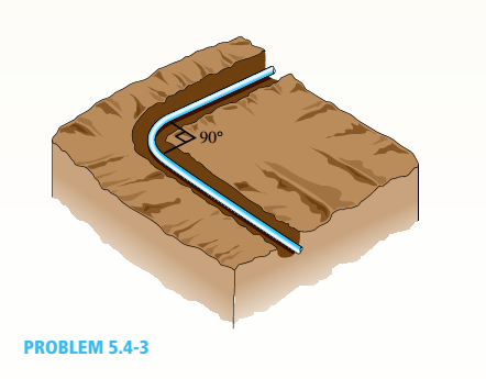
A 4.75-in, outside diameter polyethylene pipe designed to carry chemical waste is placed in a trench and bent around a quarter-circular 90° bend (see figure). The bent section of the pipe is 52 ft long.
- Determine the maximum compressive strain
- If the normal strain cannot exceed 6.1 × 10⁻³ , what is the maximum diameter of the pipe?
- If d = 4.75 in., what is the minimum acceptable length of the bent section of the pipe?
Expert Solution & Answer

Trending nowThis is a popular solution!

Chapter 5 Solutions
Mechanics of Materials (MindTap Course List)
Ch. 5 - A steel wire with a diameter of d = 1/16 in. is...Ch. 5 - A copper wire having a diameter ofd = 4 mm is bent...Ch. 5 - A 4.75-in, outside diameter polyethylene pipe...Ch. 5 - A cantilever beam AB is loaded by a couple M0at...Ch. 5 - A thin strip of steel with a length of L =19 in....Ch. 5 - A bar of rectangular cross section is loaded and...Ch. 5 - A simply supported beam with a length L = 10 ft...Ch. 5 - A cantilever beam is subjected to a concentrated...Ch. 5 - A thin strip of hard copper (E = 16,000 ksi)...Ch. 5 - A steel wire (E = 200 GPa) of a diameter d = L25...
Ch. 5 - A thin, high-strength steel rule (E = 30 x 10ft...Ch. 5 - A simply supported wood beam AB with a span length...Ch. 5 - Beam ABC has simple supports at A and B and an...Ch. 5 - A simply supported beam is subjected to a in early...Ch. 5 - Each girder of the lift bridge (sec figure) is 180...Ch. 5 - A freight-car axle AS is loaded approximately as...Ch. 5 - A seesaw weighing 3 lb/ft of length is occupied by...Ch. 5 - During construction of a highway bridge, the main...Ch. 5 - The horizontal beam ABC of an oil-well pump has...Ch. 5 - A railroad tie (or sleeper) is subjected to two...Ch. 5 - A fiberglass pipe is lifted by a sling, as shown...Ch. 5 - A small dam of height h = 2.0 m is constructed of...Ch. 5 - Determine the maximum tensile stress (7, (due to...Ch. 5 - Determine the maximum bending stress emaxdue to...Ch. 5 - A simple beam A B of a span length L = 24 ft is...Ch. 5 - Determine the maximum tensile stress erand maximum...Ch. 5 - A cantilever beam A3, loaded by a uniform load and...Ch. 5 - A canti lever beam A B of a n isosceles t...Ch. 5 - A cantilever beam, a C12 x 30 section, is...Ch. 5 - A frame ABC travels horizontally with an...Ch. 5 - A beam ABC with an overhang from B to C supports a...Ch. 5 - A cantilever beam AB with a rectangular cross...Ch. 5 - A beam with a T-section is supported and loaded as...Ch. 5 - Consider the compound beam with segments AB and...Ch. 5 - A small dam of a height h = 6 ft is constructed of...Ch. 5 - A foot bridge on a hiking trail is constructed...Ch. 5 - A steel post (E=30×106) having thickness t = 1/8...Ch. 5 - Beam ABCDE has a moment release just right of...Ch. 5 - A simply supported wood beam having a span length...Ch. 5 - A simply supported beam (L = 4.5 m) must support...Ch. 5 - The cross section of a narrow-gage railway bridge...Ch. 5 - A fiberglass bracket A BCD with a solid circular...Ch. 5 - A cantilever beanie B is loaded by a uniform load...Ch. 5 - A simple beam of length L = 5 m carries a uniform...Ch. 5 - A simple beam AB is loaded as shown in the figure....Ch. 5 - A pontoon bridge (see figure) is constructed of...Ch. 5 - A floor system in a small building consists of...Ch. 5 - The wood joists supporting a plank Floor (see...Ch. 5 - A beam ABC with an overhang from B to C is...Ch. 5 - -12 A "trapeze bar" in a hospital room provides a...Ch. 5 - A two-axle carriage that is part of an over head...Ch. 5 - A cantilever beam AB with a circular cross section...Ch. 5 - A propped cantilever beam A BC (see figure) has a...Ch. 5 - A small balcony constructed of wood is supported...Ch. 5 - A beam having a cross section in the form of an un...Ch. 5 - A beam having a cross section in the form of a...Ch. 5 - Determine the ratios of the weights of four beams...Ch. 5 - Prob. 5.6.20PCh. 5 - A steel plate (called a cover ploie) having...Ch. 5 - A steel beam ABC is simply supported at A and...Ch. 5 - A retaining wall 6 ft high is constructed of...Ch. 5 - A retaining wall (Fig. a) is constructed using...Ch. 5 - A beam of square cross section (a = length of each...Ch. 5 - The cross section of a rectangular beam having a...Ch. 5 - A tapered cantilever beam A B of length L has...Ch. 5 - .2 A ligmio.irc ii supported by two vorlical beams...Ch. 5 - Prob. 5.7.3PCh. 5 - Prob. 5.7.4PCh. 5 - Prob. 5.7.5PCh. 5 - A cantilever beam AB with rectangular cross...Ch. 5 - A simple beam ABC having rectangular cross...Ch. 5 - A cantilever beam AB having rectangular cross...Ch. 5 - The shear stresses t in a rectangular beam arc...Ch. 5 - .2 Calculate the maximum shear stress tmaxand the...Ch. 5 - A simply supported wood beam is subjected to...Ch. 5 - A simply supported wood beam with overhang is...Ch. 5 - Two wood beams, each of rectangular cross section...Ch. 5 - A cantilever beam of length L = 2 m supports a...Ch. 5 - A steel beam of length L = 16 in. and...Ch. 5 - A beam of rectangular cross section (width/) and...Ch. 5 - A laminated wood beam on simple supports (figure...Ch. 5 - A laminated plastic beam of square cross section...Ch. 5 - A wood beam AB on simple supports with span length...Ch. 5 - A simply supported wood beam of rectangular cross...Ch. 5 - A square wood platform is 8 ft × 8 ft in area and...Ch. 5 - A wood beam ABC with simple supports at A and B...Ch. 5 - A wood pole with a solid circular cross section (d...Ch. 5 - A simple log bridge in a remote area consists of...Ch. 5 - A vertical pole consisting of a circular tube of...Ch. 5 - A circular pole is subjected to linearly varying...Ch. 5 - A sign for an automobile service station is...Ch. 5 - A steel pipe is subjected to a quadratic...Ch. 5 - -1 through 5.10-6 A wide-flange beam (see figure)...Ch. 5 - -1 through 5.10-6 A wide-flange beam (see figure)...Ch. 5 - -1 through 5.10-6 A wide-flange beam (see figure)...Ch. 5 - -1 through 5.10-6 A wide-flange beam (see figure)...Ch. 5 - -1 through 5.10-6 A wide-flange beam (see figure)...Ch. 5 - -1 through 5.10-6 A wide-flange beam (see figure)...Ch. 5 - A cantilever beam AB of length L = 6.5 ft supports...Ch. 5 - A bridge girder A B on a simple span of length L =...Ch. 5 - A simple beam with an overhang supports a uniform...Ch. 5 - A hollow steel box beam has the rectangular cross...Ch. 5 - A hollow aluminum box beam has the square cross...Ch. 5 - The T-beam shown in the figure has cross-sectional...Ch. 5 - Calculate the maximum shear stress tmax. in the...Ch. 5 - A prefabricated wood I-beam serving as a floor...Ch. 5 - A welded steel gird crhaving the erass section...Ch. 5 - A welded steel girder having the cross section...Ch. 5 - A wood box beam is constructed of two 260 mm × 50...Ch. 5 - A box beam is constructed of four wood boards as...Ch. 5 - Two wood box beams (beams A and B) have the same...Ch. 5 - A hollow wood beam with plywood webs has the...Ch. 5 - A beam of a T cross section is formed by nailing...Ch. 5 - The T-beam shown in the figure is fabricated by...Ch. 5 - A steel beam is built up from a W 410 × 85 wide...Ch. 5 - The three beams shown have approximately the same...Ch. 5 - Two W 310 × 74 Steel wide-flange beams are bolted...Ch. 5 - A pole is fixed at the base and is subjected to a...Ch. 5 - A solid circular pole is subjected to linearly...Ch. 5 - While drilling a hole with a brace and bit, you...Ch. 5 - An aluminum pole for a street light weighs 4600 N...Ch. 5 - A curved bar ABC having a circular axis (radius r...Ch. 5 - A rigid Trame ABC is formed by welding two steel...Ch. 5 - A palm tree weighing 1000 lb is inclined at an...Ch. 5 - A vertical pole of aluminum is fixed at the base...Ch. 5 - Because of foundation settlement, a circular tower...Ch. 5 - A steel bracket of solid circular cross section is...Ch. 5 - A cylindrical brick chimney of height H weighs w =...Ch. 5 - A flying but tress transmit s a load P = 25 kN,...Ch. 5 - A plain concrete wall (i.e., a wall with no steel...Ch. 5 - A circular post, a rectangular post, and a post of...Ch. 5 - Two cables, each carrying a tensile force P = 1200...Ch. 5 - Prob. 5.12.16PCh. 5 - A short column constructed of a W 12 × 35...Ch. 5 - A short column with a wide-flange shape is...Ch. 5 - A tension member constructed of an L inch angle...Ch. 5 - A short length of a C 200 × 17.1 channel is...Ch. 5 - The beams shown in the figure are subjected to...Ch. 5 - The beams shown in the figure are subjected to...Ch. 5 - A rectangular beam with semicircular notches, as...Ch. 5 - A rectangular beam with semicircular notches, as...Ch. 5 - A rectangular beam with notches and a hole (see...
Knowledge Booster


Learn more about
Need a deep-dive on the concept behind this application? Look no further. Learn more about this topic, mechanical-engineering and related others by exploring similar questions and additional content below.Similar questions
- A slightly tapered bar AB of rectangular cross section and length L is acted upon by a force P (see figure). The width of the bar varies uniformly From b2at end A to b1at end B. The thickness t is constant. (a) Determine the strain energy U of the bar. (b) Determine the elongation ?? of the bar by equating the strain energy to the work done by the force P.arrow_forwardA prismatic bar AD of length L, cross-sectional area A. and modulus of elasticity E is subjected to loads 5P, 3P, and P acting at points B, C, and D, respectively (see figure). Segments AB, BC, and CD have lengths L/6, L/2, and L/3, respectively. (a) Obtain a formula for the strain energy U of the bar. (b) Calculate the strain energy if P = 6 kips, L = 52 in., A = 2.76 in2, and the material is aluminum with E = 10.4 × 10⁶ psi.arrow_forwardAn clement of material in plane strain (see figure) is subjected to strains ex= 480 × 10-6, Ey= 70 × l0-6, and yxy= 420 × l0-6. Determine the following quantities: (a) the strains for an element oriented at an angle 0 = 75°, (b) the principal strains, and (c) the maximum shear strains. Show the results on sketches of properly oriented elements.arrow_forward
- A copper wire having a diameter ofd = 4 mm is bent into a circle and held with the ends just touching (see figure), If the maximum permissible strain in the copper is = 0.0024, what is the shortest length L of wire that can be used? If L = 5.5 m, what is the maximum acceptable diameter of the wire if the maximum normal strain must remain below yield? Assume E = 120 GPa and(7K= 300 MPa.arrow_forwardA plastic-lined steel pipe has the cross-sectional shape shown in the figure. The steel pipe has an outer diameter d1= 100 mm and an inner diameter d2= 94 mm. The plastic liner has an inner diameter d1= 82 mm. The modulus of elasticity of the steel is 75 times the modulus of the plastic. Determine the allowable bending moment Mallowif the allowable stress in the steel is 35 M Pa and in the plastic is 600 kPa. If pipe and liner diameters remain unchanged, what new value of allowable stress for the steel pipe will result in the steel pipe and plastic liner reaching their allowable stress values under the same maximum moment (i.e., a balanced design)? What is the new maximum moment?arrow_forwardA thin-walled circular tube and a solid circular bar of the same material (see figure) are subjected to torsion. The tube and bar have the same cross-sectional area and the same length. What is the ratio of the strain energy U1in the tube to the strain energy U2in the solid bar if the maximum shear stresses are the same in both cases? (For the tube, use the approximate theory for thin-walled bars.)arrow_forward
- A thin strip of steel with a length of L =19 in. and thickness of t = 0,275 in. is bent by couples M0(see figure). The deflection at the midpoint of the strip (measured from a line joining its end points) is found to be 0.30 in. Determine the longitudinal normal strain ë at the top surface of the strip. If allowable strain £a= 0-0008, what is the maximum acceptable thickness of the strip? If allowable strain £a= 0.0008, t = 0.275 in., and L = 32 in., what is deflection S? If allowable strain sa= 0.0008, t = 0.275 in., and the deflection cannot exceed 1,0 in., what is the maximum permissible length of the strip?arrow_forwardThe cross section of a beam made of thin strips of aluminum separated by a lightweight plastic is shown in the figure. The beam has width b = 3.0 in., the aluminum strips have thickness t = 0.1 in., and the plastic segments have heights d = 1.2 in. and 3d = 3.6 in. The total height of the beam is h = 6.4 in. The moduli of elasticity for the aluminum and plastic are EM= 11 X 106 psi and Ep= 440 X 10* psi, respectively. Determine the maximum stresses trAiand pin the aluminum and plastic, respectively, due to a bending moment of 6,0 kip-in.arrow_forwardThe cross section of a slit circular tube of constant thickness is shown in the figure, Show that the distance e from the center of the circle to the shear center S is equal to 2r in the figure part a. Find an expression for e if flanges with the same thickness as that of the tube arc added, as shown in the figure part b.arrow_forward
- A circular aluminum tube of length L = 600 mm is loaded in compression by forces P (see figure). The outside and inside diameters are d2= 75 mm and d1= 63 mm, respectively. A strain gage is placed on the outside of the lube to measure normal strains in the longitudinal direction. Assume that E = 73 GPa and Poissons ratio is v = 0.33. (a) IF the compressive stress in the tube is 57 MPa, what is the load P? (b) If the measured strain is e = 78 J X 10-6, what is the shorteningarrow_forwardThe bar ABC shown in the figure is loaded by a force P acting at end C and by a force Q acting at the midpoint B. The bar has a constant axial rigidity EA. (a) Determine the strain energy U1of the bar when the Force P acts alone (Q = 0). (b) Determine the strain energy U2when the force Q acts alone (P = 0). (c) Determine the strain energy U3when the Forces P and Q act simultaneously upon the bararrow_forwardA beam with a T-section is supported and loaded as shown in the figure. The cross section has width b = 2 1/2 in., height c = 3 in., and thickness t = 3/8 in. Determine the maximum tensile and compressive stresses in the beam. If the allowable stresses in tension and compression are 18 ksi and 12 ksi, respectively, what is the required depth h of the beam? Assume that thickness t remains at 3/8 in. and that flange width/) = 2.5 in. Find the new values of loads P and q so that the allowable tension (18 ksi) and compression (12 ksi) stresses are reached simultaneously for the beam. Use the beam cross section in part (a) (see figure) and assume that Lh and L3are unchanged.arrow_forward
arrow_back_ios
SEE MORE QUESTIONS
arrow_forward_ios
Recommended textbooks for you
 Mechanics of Materials (MindTap Course List)Mechanical EngineeringISBN:9781337093347Author:Barry J. Goodno, James M. GerePublisher:Cengage Learning
Mechanics of Materials (MindTap Course List)
Mechanical Engineering
ISBN:9781337093347
Author:Barry J. Goodno, James M. Gere
Publisher:Cengage Learning
An Introduction to Stress and Strain; Author: The Efficient Engineer;https://www.youtube.com/watch?v=aQf6Q8t1FQE;License: Standard YouTube License, CC-BY