
Concept explainers
Videos
With regard to the circuit presented in Fig. 9.42, (a) obtain an expression for v(t) which is valid for all t > 0; (b) calculate the maximum inductor current and identify the time at which it occurs; (c) determine the settling time.
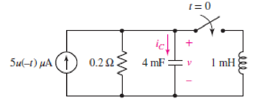
FIGURE 9.42
(a)
Find the equation for voltage
Answer to Problem 16E
The equation of voltage is
Explanation of Solution
Formula used:
The expression for the exponential damping coefficient is as follows:
Here,
The expression for the resonating frequency is as follows:
Here,
The expression for the two solutions of the characteristic equation of a parallel
Here,
Here,
Calculation:
The redrawn circuit is shown in Figure 1 as follows:
Refer to the Figure 1,
At
The current across inductor is zero because inductor is not energized.
The expression for voltage
Here,
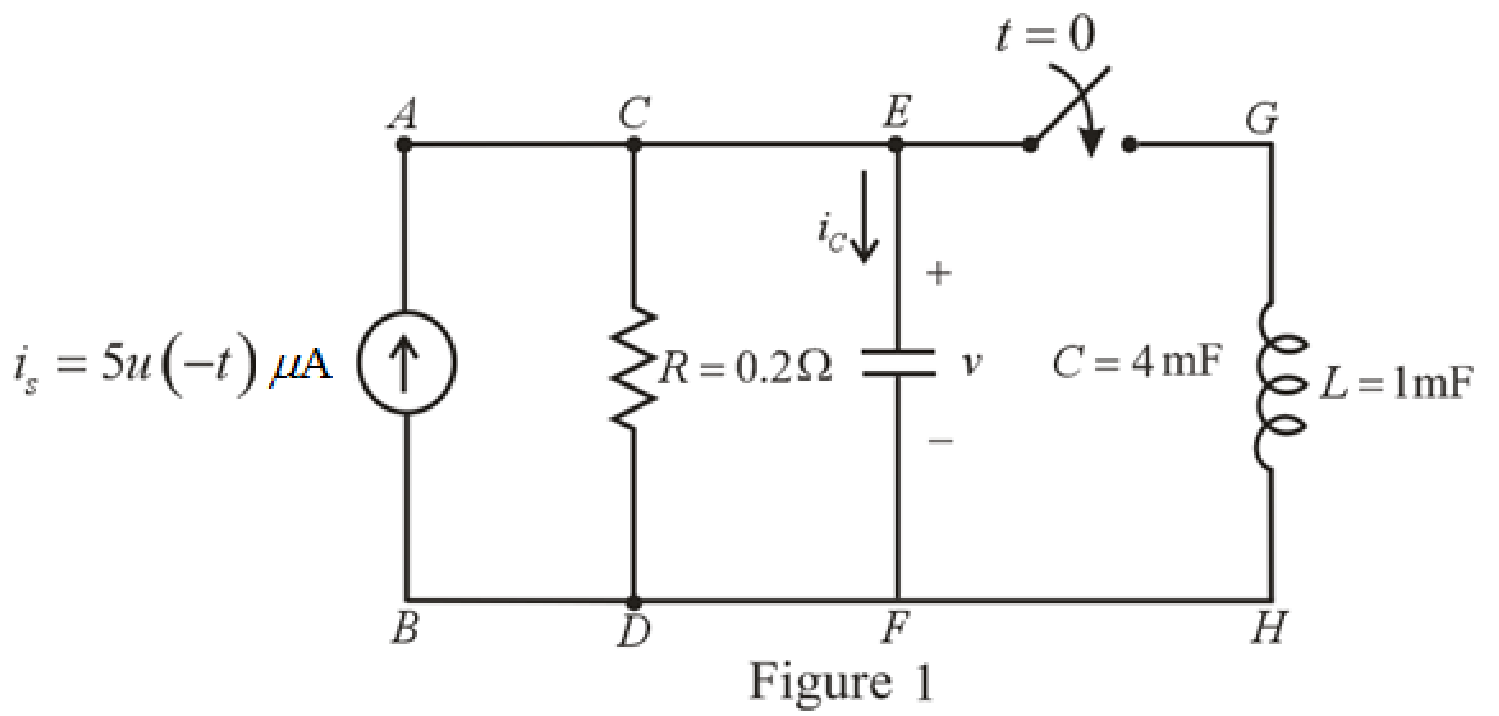
The redrawn circuit at
Refer to the Figure 2:
The expression for the voltage across capacitor at
Substitute
The expression for the natural response of voltage for capacitor in the parallel
Substitute
Rearrange for
At
Therefore,
So,
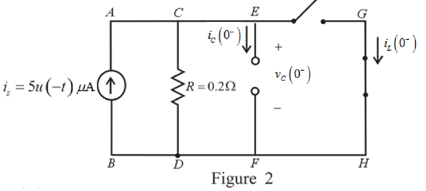
The redrawn circuit is shown in Figure 3 as follows:
Refer to the Figure 3:
The current across resistor
The expression for KCL at node
Here,
Substitute
The expression for current flowing through capacitor for
Here,
At
The circuit diagram is redrawn as shown in Figure 4 for
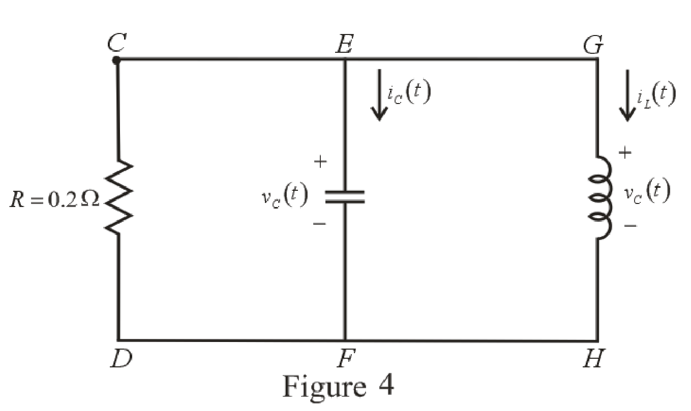
Refer to the redrawn Figure 4:
Substitute
Substitute
As value of exponential frequency
Substitute
Substitute
Differentiate equation (6) both the sides with respect to time
Substitute
Substitute
Substitute
Rearrange for
Rearrange for
Substitute
Substitute
Therefore, voltage across inductor
Conclusion:
Thus, the voltage
(b)
Find the maximum inductor current and the time of occurrence.
Answer to Problem 16E
The maximum inductor current
Explanation of Solution
Calculation:
Refer to the Figure 4:
The expression for inductor current is:
Substitute
For the maximum positive value of inductor current, take the derivative of its equation and then, equate it to zero to find the time at which maximum value of current occurs.
Differentiate equation (14) both the sides with respect to time
Equate the equation to zero.
Rearrange the equation.
Take log both the sides.
Rearrange for
Substitute
This is the maximum inductor current.
Conclusion:
Thus, the maximum inductor current is
(c)
Find the settling time.
Answer to Problem 16E
The settling time of the voltage
Explanation of Solution
Calculation:
The settling time is the time at which inductor current reaches to
Substitute
The settling time is the time at which the inductor current is decreased to
Equation (17) is solved by scientific calculator which can determine the value of time
Conclusion:
Thus, the settling time of the inductor current
Want to see more full solutions like this?
Chapter 9 Solutions
Loose Leaf for Engineering Circuit Analysis Format: Loose-leaf


- Using the diagram capacitor circuit and values provided, find ZC1, Z T, i, VR1, and Vc1arrow_forwardThe voltage pulse applied to the 100 mH inductor shown is 0 for t<0. and is given by the expression v(t)=20te−10t V for t>0. Also assume i=0 for t≤0. Sketch the voltage as a function of time.arrow_forward2. 7.22 The switch in the circuit has been in the left positionfor a long time. At t=0 it moves to the right position and stays there. 1. a) Write the expression for the capacitor voltage, v(t), for t≥0arrow_forward
- In response to a change introduced by a switch at t = 0, the current flowing through a 100 μF capacitor, defined in accordance with the passive sign convention, was observed to be i(t) = −0.4e−0.5t mA (for t > 0). If the final energy stored in the capacitor (at t = ∞) is 0.2 mJ, determine υ(t) for t ≥ 0.arrow_forwardThe voltage pulse applied to the 100 mH inductor shown is 0 for t<0 and is given by the expression v(t)=20te−10t V for t>0. Also assume i=0 for t≤0. Sketch the current as a function of time.arrow_forwardAn inductance of 1 H, a resistance of 8 Ω and capacitance of 0.04 F are connected in series with a variable voltage E = 50 sin 3t. Find the current and charge in the system, given the initial conditions q = 0 and l = 0 when t = 0, using method of solution of higher order linear ordinary differential equation.arrow_forward
- The current in a 20 mH inductor is known to be i=40 mA,t≤0; i=A1e−10,000t+A2e−40.000tA,t≥0. The voltage across the inductor (passive sign convention) is 28 V at t=0. 1. Find the expression for the voltage across the inductor for t>0. 2. Find the time, greater than zero, when the power at the terminals of the inductor is zero.arrow_forwardThe circuit elements in the circuit L=50 mH, and C=0.2 μF. The initial inductor current is−45 mA and the initial capacitor voltage is 15 V. The resistance is increased to250 Ω. Find the expression for v(t) for t≥0.arrow_forwardTwo capacitors, of capacitance 3µF and 5µF, are connected as shown to batteries A and B which have EMF 4 V and 12 V respectively. What is the energy stored in each of the capacitors? Calculate also the stored energy in each capacitor when the terminals of battery A are reversed, and when the battery B is disconnected, and the points X and Y are connected together.arrow_forward
- A 30 μF capacitor is connected in parallel with a coil of inductance 50 mH andunknown resistance R across a 120 V, 50 Hz supply. If the circuit has an overallpower factor of unity, find (a) the value of R, (b) the current in the coil, and (c)the supply current.arrow_forwardThe voltage pulse applied to the 100 mH inductor shown is 0 for t<0 and is given by the expressionv(t)=20te−10t V for t>0. Also assume i=0 for t≤0.. Find the inductor current as a function of time.arrow_forwardDesign an electrical circuit consists of the following elements, two resistance, two inductance, and one capacitance, obtain the parameters z12, y22, h21, and A.arrow_forward
 Introductory Circuit Analysis (13th Edition)Electrical EngineeringISBN:9780133923605Author:Robert L. BoylestadPublisher:PEARSON
 Delmar's Standard Textbook Of ElectricityElectrical EngineeringISBN:9781337900348Author:Stephen L. HermanPublisher:Cengage Learning
 Programmable Logic ControllersElectrical EngineeringISBN:9780073373843Author:Frank D. PetruzellaPublisher:McGraw-Hill Education
 Fundamentals of Electric CircuitsElectrical EngineeringISBN:9780078028229Author:Charles K Alexander, Matthew SadikuPublisher:McGraw-Hill Education
 Electric Circuits. (11th Edition)Electrical EngineeringISBN:9780134746968Author:James W. Nilsson, Susan RiedelPublisher:PEARSON
 Engineering ElectromagneticsElectrical EngineeringISBN:9780078028151Author:Hayt, William H. (william Hart), Jr, BUCK, John A.Publisher:Mcgraw-hill Education,