
Videos
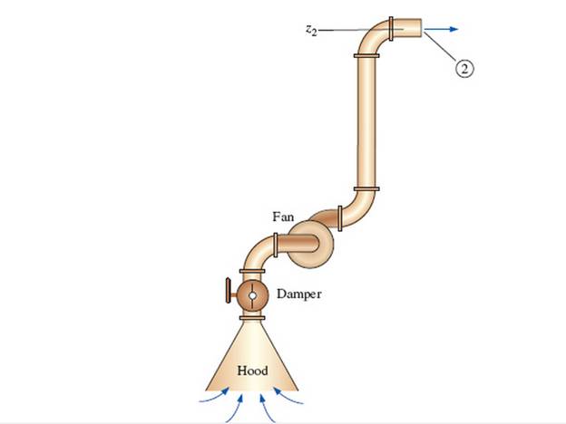
A local ventilation system (a hood and duct system) is used to remove air and contaminants produced by a welding operation (Fig. P 14-55E). The inner diameter (ID) of the duct is D = 9.06 in, its average roughness is 0.0059 in, and its total length is L = 34.0 ft. There are three elbows along the duct, each with a minor loss coefficient of 0.21. Literature from the hood manufacturer lists the hood entry loss coefficient as 4.6 based on duct velocity. When the damper is fully open, its loss coefficient is 1.8. A squirrel cage centrifugal fan with a 9.0-in inlet is available. Its performance data fit a parabolic curve of the form

The volume flow rate.
Answer to Problem 55EP
The volume flow rate is
Explanation of Solution
Given Information:
The inner diameter of the duct is
Expression for steady energy equation from point 1 in the stagnant air region to point 2 at the duct outlet
Here, the required head for the fan is
Expression for the total head loss
Here, the velocity of the air is
Expression for Reynold's number
Here, the kinematic viscosity is
Expression for relative roughness
Here, the roughness of the pipe is
Expression for the friction factor
Expression for the volume flow rate
Here, the area of the pipe is
Expression for the area of the pipe
Substitute
Expression to convert the shutoff head from inches of water column to inches of air column
Here, the density of the water is
Expression to convert
Calculation:
Refer to the Table-A-9E, "Properties of air at 1 atm pressure" to obtain the density of the air as
Substitute
Substitute
Substitute
Substitute
Substitute
Substitute
Substitute
Substitute
Substitute
Substitute
Since at the operating point the available head and the required head are equal, therefore equate equation (XII) and (XIII).
Solve Equation (XII) and Equation (XIV) to obtain the value of velocity as
Substitute
Conclusion:
The volume flow rate is
Want to see more full solutions like this?
Chapter 14 Solutions
Fluid Mechanics: Fundamentals and Applications


- Suppose the pump of Fig. P14–23 is operating atfree delivery conditions. The pipe, both upstream and downstreamof the pump, has an inner diameter of 2.0 cm andnearly zero roughness. The minor loss coefficient associatedwith the sharp inlet is 0.50, each valve has a minor loss coefficientof 2.4, and each of the three elbows has a minor losscoefficient of 0.90. The contraction at the exit reduces thediameter by a factor of 0.60 (60% of the pipe diameter), andthe minor loss coefficient of the contraction is 0.15. Note thatthis minor loss coefficient is based on the average exit velocity,not the average velocity through the pipe itself. The total length of pipe is 6.7 m, and the elevation difference is (z1 - z2)= 4.6 m. Estimate the volume flow rate through this pipingsystem. Complete Answer, Thank youarrow_forward1. In laminar flow, which is correct?BJ: higher Re value has higher friction factorJB: lower Re value has higher friction factorGroup of answer choices A. BJ is false and JB is true B. BJ is true and JB is false C. BJ is false and JB is false D. BJ is true and JB is true 2.In turbulent flow, which is correct?BJ: higher Re value has lower friction factorJB: lower Re value has higher friction factorGroup of answer choices A.BJ is true and JB is true B.BJ is false and JB is false C. BJ is false and JB is true D. BJ is true and JB is false 3. In a system with 4 reservoirs and 1 pipe junction, how many continuity equations are formulable?Group of answer choices A. 2 B. 3 C. 5 D. 4 E. 1arrow_forwardinclude a free body diagram Seawater is to be pumped into a large tank at a rate of 165 kg/min. The tank is opwn to atmostsphere and the water enters the tank from a 80 m height. The overall efficiency of the motor pump unit is 75 percent and the motor consumes electricity at a rate of 3.2 KW. If the irreversible headloss in the piping is 7 m, the velocity of the water (in m/s) at the tank inlet isA. 6.21B. 7.12C. 8.7D. 5.05arrow_forward
- A piping system involves sharp turns, and thus large minor head losses. One way of reducing the head loss is to replace the sharp turns by circular elbows. What is another way?arrow_forwardThe effect of rounding of a pipe exit on the loss coefficient is (a) negligible, (b) somewhat significant, or (c) very significant.arrow_forwardA water fountain is to be installed at a remote location by attaching a cast iron pipe directly to a water main through which water is flowing at 70°F and 60 psig. The entrance to the pipe is sharp-edged, and the 70-ft-long piping system involves three 90° miter bends without vanes, a fully open gate valve, and an angle valve with a loss coefficient of 5 when fully open. If the system is to provide water at a rate of 15 gal/min and the elevation difference between the pipe and the fountain is negligible, determine the minimum diameter of the piping system.arrow_forward
- Air is flowing in a circular duct. The air flow rate is Q=2000 ft3/min. The diameter of the duct is D=14 in. (2) Determine the friction loss per 100 ft, hL_________inH2Oarrow_forwardA clothes dryer discharges air at 1 atm and 120°F at a rate of 1.2 ft3/s when its 5-in-diameter, well-rounded vent with negligible loss is not connected to any duct. Determine the flow rate when the vent is connected to a 15-ft-long, 5-in-diameter duct made of galvanized iron, with three 90° flanged smooth bends. Take the friction factor of the duct to be 0.019, and assume the fan power input to remain constant.arrow_forwardCan you use the friction factor for turbulent flow in a smooth circular tube to predict the fiction factor in an internally finned tube by using the hydraulic diameter?arrow_forward
- CORRECT LETTER PLS 1. In laminar flow, which is correct?BJ: higher Re value has higher friction factorJB: lower Re value has higher friction factorGroup of answer choices A. BJ is false and JB is true B. BJ is true and JB is false C. BJ is false and JB is false D. BJ is true and JB is true 2.In turbulent flow, which is correct?BJ: higher Re value has lower friction factorJB: lower Re value has higher friction factorGroup of answer choices A.BJ is true and JB is true B.BJ is false and JB is false C. BJ is false and JB is true D. BJ is true and JB is false 3. In a system with 4 reservoirs and 1 pipe junction, how many continuity equations are formulable?Group of answer choices A. 2 B. 3 C. 5 D. 4 E. 1arrow_forwardIn the diesel oil transfer facility (ρ rel = 0.85), from the storage tank to the consumption tank, we want to install a pump to circulate a flow of 45 lt / s. The 400m long pipe is cast 150mm in diameter and consists of a check valve, a gate valve and 2 commercial medium radius elbows. The consumption tank is pressurized to 3.8 bar of manometric pressure. Determine the drive power of the pump in kW if its performance is 68%. Additional data, load loss factors: 1. Check valve Kr = 1.5 2. Gate valve open Kv = 0.21 3. Commercial elbow of mean radius Kc = 0.75, for each elbow 4. Storage tank outlet sharp angles Ks = 0.5 5. Entrance to consumption tank Ke = 1 6. Pipe friction factor f = 0.025arrow_forwardAn open cistern on top of a tower and a reservoir are connected by a 1000 m long, 0.1 m diameter old sewerpipe. The pipe coveys discharge at a rate of 5 L s-1 at 20°C to the lower reservoir. a)Draw the HGL and EGL.b) How tall does the water tower need to be in order to meet discharge demands, consideringboth minor and major losses?arrow_forward
 Elements Of ElectromagneticsMechanical EngineeringISBN:9780190698614Author:Sadiku, Matthew N. O.Publisher:Oxford University Press
 Mechanics of Materials (10th Edition)Mechanical EngineeringISBN:9780134319650Author:Russell C. HibbelerPublisher:PEARSON
 Thermodynamics: An Engineering ApproachMechanical EngineeringISBN:9781259822674Author:Yunus A. Cengel Dr., Michael A. BolesPublisher:McGraw-Hill Education
 Control Systems EngineeringMechanical EngineeringISBN:9781118170519Author:Norman S. NisePublisher:WILEY
 Mechanics of Materials (MindTap Course List)Mechanical EngineeringISBN:9781337093347Author:Barry J. Goodno, James M. GerePublisher:Cengage Learning
 Engineering Mechanics: StaticsMechanical EngineeringISBN:9781118807330Author:James L. Meriam, L. G. Kraige, J. N. BoltonPublisher:WILEY