
Concept explainers
Videos
The vertical stress
Because this equation is inconvenient to solve manually, it has been reformulated as
FIGURE P20.27
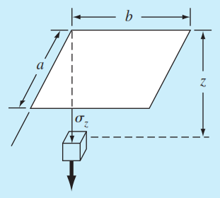
TABLE P20.27
| m | n = 1.2 | n = 1.4 | n = 1.6 |
| 0.1 | 0.02926 | 0.03007 | 0.03058 |
| 0.2 | 0.05733 | 0.05894 | 0.05994 |
| 0.3 | 0.08323 | 0.08561 | 0.08709 |
| 0.4 | 0.10631 | 0.10941 | 0.11135 |
| 0.5 | 0.12626 | 0.13003 | 0.13241 |
| 0.6 | 0.14309 | 0.14749 | 0.15027 |
| 0.7 | 0.15703 | 0.16199 | 0.16515 |
| 0.8 | 0.168430 | 0.17389 | 0.17739 |
where
Want to see the full answer?
Check out a sample textbook solution
Chapter 20 Solutions
EBK NUMERICAL METHODS FOR ENGINEERS
Additional Engineering Textbook Solutions
Fundamentals of Differential Equations (9th Edition)
Basic Technical Mathematics
Advanced Engineering Mathematics
Precalculus (6th Edition)
Mathematics for the Trades: A Guided Approach (11th Edition) (What's New in Trade Math)


- ABC element with rectangular section shown in the figure is in the (x-z) plane. Find the point at which the stress must be compared to the safety stress of the material on the most stressed cross section and determine the value of this stress. Use the Tresca hypothesis. Note: Also consider the effect of normal force. Neglect the effect of the shear force. 180cm В A F E 1.5cm 25kN y 130cm y G 3 сm 60kN Cross-sectionarrow_forwardQUESTION 1 Figure Q1 shows a frame structure that is connected to a cable with a tension force of 150 N. Determine the resultant internal loadings acting on the cross section at points E and F of the frame. 3 m 1 m I m F 100 N/m B E -2 m- -2 m- 1 m 1 m 30° Figure Q1 150 Narrow_forwardA rectangular steel block is 76 mm long in the x direction, 50 mm long in the y direction, and 100 mmlong in the z direction. The block is subjected to a triaxial loading consisting of three axial forces asfollows: 214 kN tension in the x direction, 268 kN compression in the y direction, and 241 kN tensionin the z direction. If v = 0.30 and E = 200 GPa, determine the axial load in the x direction that wouldproduce the same deformation in the y direction as the original loading.arrow_forward
- 3. The rigid bar AB is supported by two rods made of the same material. If the bar is horizontal before the load P is applied, find the distance x that locates the position where P must act if the bar is to remain horizontal. Neglect the weight of bar AB. L = 3 ft A = 0.2 in.2 L = 2 ft A = 0.4 in.2 х X B 10 ftarrow_forwardThe rod BD is made of material with G1= 124 GPa has a diameter 34 mm is bonded to the tube CA at point B, the tube made of material with G2=211 GPa has an outer diameter 73 mm and wall thickness of 10 mm. If T1=579 N.m and T2=1042 N.m, answer the following questions: The maximum shear stress of the rod BD is The maximum shear stress of the tube CA is The maximum shear stress of the assembly is The angle of twist between D and B is The angle of twist between C and A is The angle of twist at D is Your answer The angle of twist between C and B is Your answer The reaction at point A isarrow_forwardA brass bar having a cross sectional area of 500 mm2 is subjected to an axial force as shown in the figure. Determine the total elongation of the bar. Take E=80 GPa. A В 100 kN + 80 kN 50 kN -- 30 kN 500 mm 1000 mm 1200 mm-arrow_forward
- A uniformly tapering circular rod is subjected to load as shown in the figure . Determine the elongation of the rod. Take E = 2.1 * 105 N/mm2.arrow_forwardThe bar shown in diagram is subjected to a tensile load of 150 kN. If the stress in the middle portion is limited to 160 N/mm2, determine the diameter of the middle portion. Find also the length of the middle portion if the total elongation of the bar is to be 0.25 cm. Young's modulus is given as equal to 2.0 × 10⁵ N/mm2. 150 KN ➜ 10 cm DIA 45 cm 10 cm DIA 150 KNarrow_forward8000 mm3 aluminium cube is stressed in 3 mutually perpendicular direction x,y and z. The stresses in these directions are σx = 50 kPaσy = 80 kPaσz = -100 kPaDetermine the volumetric strain and change in volume. ν is 0.34 and E is 71 GPaarrow_forward
- A load F of 500 N is applied in the negative x-direction on rod OA, and a load P of 200 N is applies in the negative z-direction at point B on rod AB. Assume rod AB is fixed to rod OA and rod OA is fixed along the left side to a wall. Point C is along the frontmost edge of rod OA, in the XZ plane. 0.5 m 0.1 marrow_forwardA round Steel rod of 50 mm diameter is bent into an arc of radius 10m. What is the maximum stress in the rod? Take E = 2×10⁵ N/mm2arrow_forwardThe cross sections of two hollow bars made of the same material are concentric circles as shown in the figure. It is given that r3 > rland r4 > r2, and that the areas of the cross-sections are the same. J1 and J2 are the torsional rigidities of the bars on the left and right, respectively. The ratio J2/J1 is r3 r2arrow_forward
 Elements Of ElectromagneticsMechanical EngineeringISBN:9780190698614Author:Sadiku, Matthew N. O.Publisher:Oxford University Press
 Mechanics of Materials (10th Edition)Mechanical EngineeringISBN:9780134319650Author:Russell C. HibbelerPublisher:PEARSON
 Thermodynamics: An Engineering ApproachMechanical EngineeringISBN:9781259822674Author:Yunus A. Cengel Dr., Michael A. BolesPublisher:McGraw-Hill Education
 Control Systems EngineeringMechanical EngineeringISBN:9781118170519Author:Norman S. NisePublisher:WILEY
 Mechanics of Materials (MindTap Course List)Mechanical EngineeringISBN:9781337093347Author:Barry J. Goodno, James M. GerePublisher:Cengage Learning
 Engineering Mechanics: StaticsMechanical EngineeringISBN:9781118807330Author:James L. Meriam, L. G. Kraige, J. N. BoltonPublisher:WILEY